| Previous | UML Classes | Table of Contents | UML Packages | Next |
(Normative)
This annex describes the general properties of UML diagrams and how they relate to a UML (repository) model and to elements
of this. It also introduces the different diagram types of UML.
A UML model consists of elements such as packages, classes, and associations. The corresponding UML diagrams are graphical
representations of parts of the UML model. UML diagrams contain graphical elements (nodes connected by paths) that represent
elements in the UML model. As an example, two associated classes defined in a package will, in a diagram for the package,
be represented by two class symbols and an association path connecting these two class symbols.
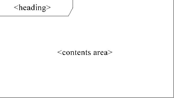
Each diagram has a contents area. As an option, it may have a frame and a heading
as shown in Figure A.1.
Figure A.1
The frame is a rectangle. The frame is primarily used in cases where the diagrammed element has graphical border elements,
like ports for classes and components (in connection with composite structures), and entry/exit points on statemachines. In
cases where not needed, the frame may be omitted and implied by the border of the diagram area provided by a tool. In case
the frame is omitted, the heading is also omitted.
The diagram contents area contains the graphical symbols; the primary graphical symbols define the type of the diagram (e.g.,
a class diagram is a diagram where the primary symbols in the contents area are class symbols).
The heading is a string contained in a name tag (rectangle with cutoff corner) in the upper leftmost corner of the rectangle,
with the following syntax:
[<kind>]<name>[<parameters>]
The heading of a diagram represents the kind, name, and parameters of the namespace enclosing or the model element owning
elements that are represented by symbols in the contents area. Most elements of a diagram contents area represent model elements
that are defined in the namespace or are owned by another model element.
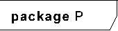
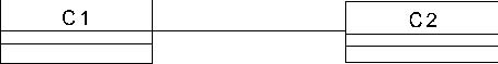
As an
example, Figure A.2 is a class diagram
of a package P: classes C1 and C2 are defined in the namespace of the package P.
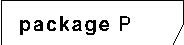
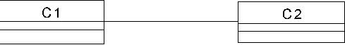
Figure A.2 - Class diagram of package P
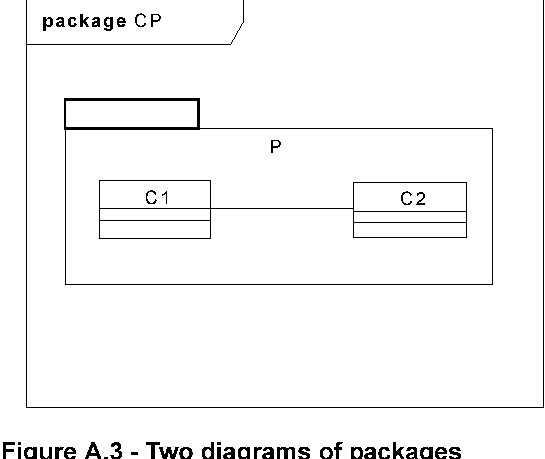
Figure A.3
illustrates that a package symbol for package P (in some containing package CP) may show the same contents as the class diagram
for the package. i) is a diagram for package CP with graphical symbols representing the fact that the CP package contains
a package P. ii) is a class diagram for this package P. Note that the package symbol in i) does not have to contain the class
symbols and the association symbol; for more realistic models, the package symbols will typically just have the package names,
while the class diagrams for the packages will have class symbols for the classes defined in the packages.

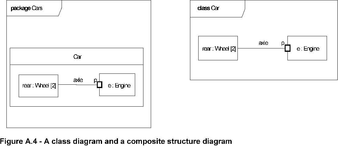
In
Figure A.4
i) is a class diagram for the package Cars, with a class symbol representing the fact that the Cars package contains a class
Car. ii) is a composite structure diagram for this class Car. The class symbol in i) does not have to contain the structure
of the class in a compartment; for more realistic models, the class symbols will typically just have the class names, while
the composite structure diagrams for the classes will have symbols for the composite structures.

UML diagrams may have the following kinds of frame names as part of the heading:
• activity
• class
• component
• interaction
• package
• state machine
• use case
In addition to the long form names for diagram heading types, the following abbreviated forms can also be used:
• act (for activity frames)
• cmp (for component frames)
• sd (for interaction frames)
• pkg (for package frames)
• stm (for state machine frames)
• uc (for use case frames)
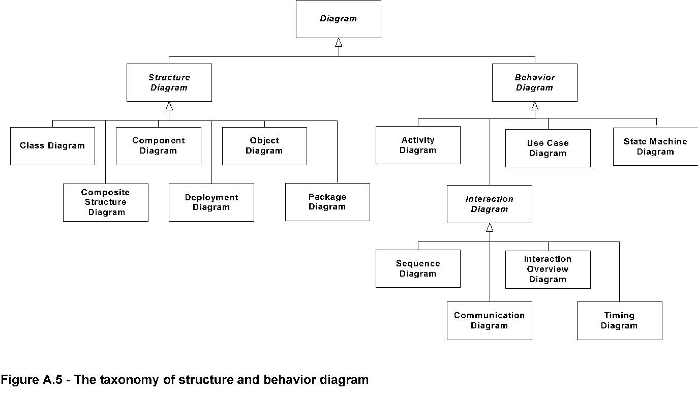
As is shown in
Figure A.5
, there are two major kinds of diagram types: structure diagrams and behavior diagrams.
Structure diagrams show the static structure of the objects in a system. That is, they depict those elements in a specification
that are irrespective of time. The elements in a structure diagram represent the meaningful concepts of an application, and
may include abstract, real-world and implementation concepts. For example, a structure diagram for an airline reservation
system might include classifiers that represent seat assignment algorithms, tickets, and a credit authorization service. Structure
diagrams do not show the details of dynamic behavior, which are illustrated by behavioral diagrams. However, they may show
relationships to the behaviors of the classifiers exhibited in the structure diagrams.
Behavior diagrams show the dynamic behavior of the objects in a system, including their methods, collaborations, activities,
and state histories. The dynamic behavior of a system can be described as a series of changes to the system over time. Behavior
diagrams can
be further classified into several other kinds as illustrated in Figure A.5.
Please note that this taxonomy provides a logical organization for the various major kinds of diagrams. However, it does not
preclude mixing different kinds of diagram types, as one might do when one combines structural and behavioral elements (e.g.,
showing a state machine nested inside an internal structure). Consequently, the boundaries between the various kinds of diagram
types are not strictly enforced.
The constructs contained in each of the thirteen UML diagrams is described in the Superstructure chapters as indicated below.
• Activity Diagram - Activities on page 307
• Class Diagram - Classes on page 21
• Communication Diagram - Interactions on page 477
• Component Diagram - Components on page 147
• Composite Structure Diagram - Composite Structures on page 167
• Deployment diagram - Deployments on page 201
•
Interaction Overview Diagram - Interactions on page 477
•
Object Diagram - Classes on page 21
•
Package Diagram -Classes on page 21
•
State Machine Diagram - State Machines on page 545
•
Sequence Diagram - Interactions on page 477
•
Timing Diagram - Interactions on page 477
•
Use Case Diagram - Use Cases on page 611