8.3.2 Connector
The connector concept is extended in the Components package to include interface based constraints and notation.
A delegation connector is a connector that links the external contract of a component (as specified by its ports) to the internal
realization of that behavior by the component’s parts. It represents the forwarding of signals (operation requests and events):
a signal that arrives at a port that has a delegation connector to a part or to another port will be passed on to that target
for handling.
An assembly connector is a connector between two components that defines that one component provides the services that another
component requires. An assembly connector is a connector that is defined from a required interface or port to a provided interface
or port.
*Generalizations
•
Connector (from InternalStructures ) on page 181 (
merge increment)
*Description
In the metamodel, a connector kind attribute is added to the Connector metaclass. Its value is an enumeration type with valid
values assembly or delegation.
*Attributes
Package BasicComponents
• kind : ConnectorKind Indicates the kind of connector.
*Associations
Issue 8976 - add ‘contract’ entry
• contract : Behavior [0..*] The set of Behaviors that specify the valid interaction patterns across the connector
*Constraints
[1] A delegation connector must only be defined between used Interfaces or Ports of the same kind (e.g., between two provided
Ports or between two required Ports ).
[2] If a delegation connector is defined between a used Interface or Port and an internal Part Classifier, then that Classifier
must have an implements relationship to the Interface type of that Port.
[3] If a delegation connector is defined between a source Interface or Port and a target Interface or Port, then the target
Interface must support a signature compatible subset of Operations of the source Interface or Port.
[4] In a complete model, if a source Port has delegation connectors to a set of delegated target Ports , then the union of
the Interfaces of these target Ports must be signature compatible with the Interface that types the source Port.
[5] An assembly connector must only be defined from a required Interface or Ports to a provided Interface or Port.
*Semantics
A delegation connector is a declaration that behavior that is available on a component instance is not actually realized by
that component itself, but by another instance that has compatible capabilities. This may be another Component or a (simple)
Class. The latter situation is modeled through a delegation connector from a Component Interface or Port to a contained Class
that functions as a Part. In that case, the Class must have an implements relationship to the Interface of the Port.
Delegation connectors are used to model the hierarchical decomposition of behavior, where services provided by a component
may ultimately be realized by one that is nested multiple levels deep within it. The word delegation suggests that concrete
message and signal flow will occur between the connected ports, possibly over multiple levels. It should be noted that such
signal flow is not always realized in all system environments or implementations (i.e., it may be design time only).
A port may delegate to a set of ports on subordinate components. In that case, these subordinate ports must collectively offer
the delegated functionality of the delegating port. At execution time, signals will be delivered to the appropriate port.
In the cases where multiple target ports support the handling of the same signal, the signal will be delivered to all these
subordinate ports.
The execution time semantics for an assembly connector are that signals travel along an instance of a connector, originating
in a required port and delivered to a provided port. Multiple connectors directed from a single required interface or port
to provided interfaces on different components indicates that the instance that will handle the signal will be determined
at execution time. Similarly, multiple required ports that are connected to a single provided port indicates that the request
may originate from instances of different component types.
The interface compatibility between provided and required ports that are connected enables an existing component in a system
to be replaced by one that (minimally) offers the same set of services. Also, in contexts where components are used to extend
a system by offering existing services, but also adding new functionality, assembly connectors can be used to link in the
new component definition. That is, by adding the new component type that offers the same set of services as existing types,
and defining new assembly connectors to link up its provided and required ports to existing ports in an assembly.
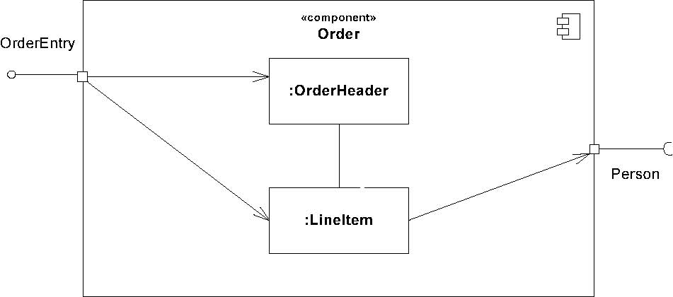
*Notation
A delegation connector is notated as a Connector from the delegating source Port to the handling target Part, and vice versa
for required Interfaces or Ports .
item
order
1
Figure 8.16 - Delegation connectors connect the externally provided interfaces of a component to the parts that realize
or require them.
An assembly connector is notated by a ball-and-socket connection between a provided interface and a required interface. This
notation allows for succinct graphical wiring of components, a requirement for scaling in complex systems.
When this notation is used to connect complex ports that are typed by multiple provided and/or required interfaces, the various
interfaces are listed as an ordered set, designated with {provided} or {required} if needed.
OrderEntry«component»

OrderEntry «component»

:Order
Order

OrderableItem OrderableItem
«component»
Product

OrderableItem
OrderableItem
«component»
:Product
Figure 8.17 - An assembly connector maps a required interface of a component to a provided interface of another component
in a certain context (definition of components, e.g., in a library on the left, an assembly of those components on the right).
Issue 8901 - replace paragraph
Where multiple components provide or require the same interface, a single symbol representing the interface can be shown,
and lines from the components can be drawn to that symbol, indicating that this interface is either a required or provided
interface for the components. This presentation option is applicable whether the interface is shown using "ball
and-socket" notation, as in Figure 8.18, or just using a required or provided interface symbol.
«component»
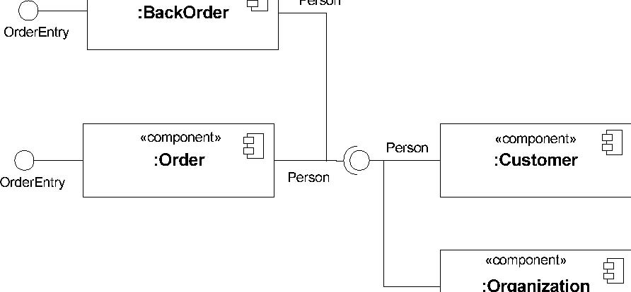
Note: Client interface is a subtype of Person interface
Figure 8.18 - As a notation abstraction, multiple wiring relationships can be visually grouped together in a component assembly.
*Changes from previous UML
The following changes from UML 1.x have been made — Connector is not defined in UML 1.4.