8.3.1 Component
A component represents a modular part of a system that encapsulates its contents and whose manifestation is replaceable within
its environment.
A component defines its behavior in terms of provided and required interfaces. As such, a component serves as a type whose
conformance is defined by these provided and required interfaces (encompassing both their static as well as dynamic semantics).
One component may therefore be substituted by another only if the two are type conformant. Larger pieces of a system’s functionality
may be assembled by reusing components as parts in an encompassing component or assembly of components, and wiring together
their required and provided interfaces.
A component is modeled throughout the development life cycle and successively refined into deployment and run-time. A component
may be manifest by one or more artifacts, and in turn, that artifact may be deployed to its execution environment. A deployment
specification may define values that parameterize the component’s execution. (See Deployment chapter).
*Generalizations
• Class (from StructuredClasses ) on page 160
Issue 8457 -add new NamedElement superclass
•
NamedElement (from Kernel , Dependencies ) on page 99
*Description
BasicComponents
A component is a subtype of Class that provides for a Component having attributes and operations, and being able to participate
in Associations and Generalizations. A Component may form the abstraction for a set of realizingClassifiers that realize its
behavior. In addition, because a Class itself is a subtype of an EncapsulatedClassifier , a Component may optionally have an
internal structure and own a set of Ports that formalize its interaction points.
A component has a number of provided and required Interfaces , that form the basis for wiring components together, either using
Dependencies , or by using Connectors. A provided Interface is one that is either implemented directly by the component or
one of its realizingClassifiers, or it is the type of a provided Port of the Component. A required interface is designated
by a Usage Dependency from the Component or one of its realizingClassifiers, or it is the type of a required Port.
PackagingComponents
A component is extended to define the grouping aspects of packaging components. This defines the Namespace aspects of a Component
through its inherited ownedMember and elementImport associations. In the namespace of a component, all model elements that
are involved in or related to its definition are either owned or imported explicitly. This may include, for example, UseCases
and Dependencies (e.g., mappings), Packages, Components, and Artifacts .
*Attributes
Package BasicComponents
• isIndirectlyInstantiated : Boolean {default = true} The kind of instantiation that applies to a Component. If false, the
component is instantiated as an addressable object. If true, the Component is defined at design-time, but at run-time (or
execution-time) an object specified by the Component does not exist, that is, the component is instantiated indirectly, through
the instantiation of its realizing classifiers or parts. Several standard stereotypes use this meta attribute (e.g., «specification»,
«focus», «subsystem»).
*Associations
Package BasicComponents
• /provided: Interface [*] The interfaces that the component exposes to its environment. These interfaces may be Realized
by the Component or any of its realizingClassifiers, or they may be the Interfaces that are provided by its public Ports .
The provided interfaces association is a derived association:
Issue 8103 -Fix typo.
context Component::provided derive: let implementedInterfaces = self.implementation->collect(impl|impl.contract) and let realizedInterfaces = RealizedInterfaces (self) and let realizingClassifierInterfaces = RealizedInterfaces (self.realizingClassifier) and let typesOfRequiredPorts = self.ownedPort.provided in
(((implementedInterfaces ->union(realizedInterfaces )->union(realizingClassifierInterfaces ))->union(typesOfRequiredPorts ))->asSet()
• /required: Interface [*] The interfaces that the component requires from other components in its environment in order to
be able to offer its full set of provided functionality. These interfaces may be Used by the Component or any of its realizingClassifiers,
or they may be the Interfaces that are required by its public Ports . The required interfaces association is a derived association:
context Component::required derive: let usedInterfaces = UsedInterfaces (self) andlet realizingClassifierUsedInterfaces = UsedInterfaces (self.realizingClassifier) and let typesOfUsedPorts = self.ownedPort.required in
((usedInterfaces ->union(realizingClassifierUsedInterfaces ))-> union(typesOfUsedPorts ))->asSet()
Issue 9109 -make realization non-derived 9119 - replace ‘Realization’ with ‘ComponentRealization ’
• realization: ComponentRealization [*] The set of Realizations owned by the Component. These realizations reference the Classifiers
of which the Component is
an abstraction (i.e., those that realize its behavior).
PackagingComponents
Issue 9088 -replace ‘ownedMember’ with ‘packagedElement’ and change explanation
• packagedElement: PackageableElement [*] The set of PackageableElement s that a Component owns. In the namespace of a component,
all model elements that are involved in or related to its definition may be owned or imported explicitly. These may include
e.g. Classes, Interfaces , Components, Packages, Use cases, Dependencies (e.g. mappings), and Artifacts . Subsets Namespace ::ownedMember.
*Constraints
No further constraints
*Additional Operations
[1] Utility returning the set of realized interfaces of a component:
def: RealizedInterfaces : (classifier : Classifier) : Interface = (classifier.clientDependency -> select(dependency|dependency.oclIsKindOf(Realization) and dependency.supplier.oclIsKindOf(Interface)))->collect(dependency|dependency.client)
[2] Utility returning the set of required interfaces of a component:
def: UsedInterfaces : (classifier : Classifier) : Interface = (classifier.supplierDependency -> select(dependency|dependency.oclIsKindOf(Usage ) and dependency.supplier.oclIsKindOf(interface)))->collect(dependency|dependency.supplier)
*Semantics
A component is a self contained unit that encapsulates the state and behavior of a number of classifiers. A component specifies
a formal contract of the services that it provides to its clients and those that it requires from other components or services
in the system in terms of its provided and required interfaces.
A component is a substitutable unit that can be replaced at design time or run-time by a component that offers equivalent
functionality based on compatibility of its interfaces. As long as the environment obeys the constraints expressed by the
provided and required interfaces of a component, it will be able to interact with this environment. Similarly, a system can
be extended by adding new component types that add new functionality.
The required and provided interfaces of a component allow for the specification of structural features such as attributes
and association ends, as well as behavioral features such as operations and events. A component may implement a provided interface
directly, or, its realizing classifiers may do so. The required and provided interfaces may optionally be organized through
ports, these enable the definition of named sets of provided and required interfaces that are typically (but not always) addressed
at run-time.
A component has an external view (or black-box view) by means of its publicly visible properties and operations. Optionally,
a behavior such as a protocol state machine may be attached to an interface, port, and to the component itself, to define
the external view more precisely by making dynamic constraints in the sequence of operation calls explicit. Other behaviors
may also be associated with interfaces or connectors to define the ‘contract’ between participants in a collaboration (e.g.,
in terms of use case, activity, or interaction specifications).
The wiring between components in a system or other context can be structurally defined by using dependencies between component
interfaces (typically on structure diagrams). Optionally, a more detailed specification of the structural collaboration can
be made using parts and connectors in composite structures, to specify the role or instance level collaboration between components
(See Chapter Composite Structures).
A component also has an internal view (or white-box view) by means of its private properties and realizing classifiers. This
view shows how the external behavior is realized internally. The mapping between external and internal view is by means of
dependencies (on structure diagrams), or delegation connectors to internal parts (on composite structure diagrams). Again,
more detailed behavior specifications such as interactions and activities may be used to detail the mapping from external
to internal behavior.
A number of UML standard stereotypes exist that apply to component. For example, «subsystem» to model large-scale components,
and «specification» and «realization» to model components with distinct specification and realization definitions, where one
specification may have multiple realizations (see the UML Standard Elements Appendix).
*Notation
A component is shown as a Classifier rectangle with the keyword «component». Optionally, in the right hand corner a component
icon can be displayed. This is a classifier rectangle with two smaller rectangles protruding from its left hand side.
QuoteInf
«component»
QuoteService

Figure 8.5 - A Component with one provided interface
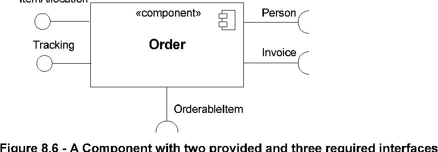 Figure 8.6 - A Component with two provided and three required interfaces
An external view of a Component is by means of Interface symbols sticking out of the Component box (external, or black-box
view). Alternatively, the interfaces and/or individual operations and attributes can be listed in the compartments of a component
box (for scalability, tools may offer way of listing and abbreviating component properties and behavior).
«component»
Order
«provided interfaces» OrderEntry Billing
«required interfaces»
Invoice create (...) registerPayment (...)
Figure 8.7 - Black box notation showing a listing of the properties of a component
For displaying the full signature of an interface of a component, the interfaces can also be displayed as typical classifier
rectangles that can be expanded to show details of operations and events.
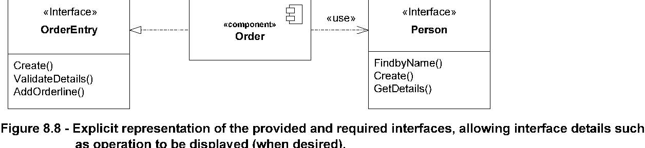 Figure 8.8 - Explicit representation of the provided and required interfaces, allowing interface details such as operation
to be displayed (when desired).
Figure 8.8 - Explicit representation of the provided and required interfaces, allowing interface details such as operation
to be displayed (when desired).
An internal, or white box view of a Component is where the realizing classifiers are listed in an additional compartment.
Compartments may also be used to display a listing of any parts and connectors, or any implementing artifacts.
Figure 8.9 - A white-box representation of a component
Order «component»
«provided interfaces» OrderEntry AccountPayable «required interfaces» Person
«realizations» OrderHeader LineItem
«artifacts» Order.jar |
|
|
|
|
|
|
|
|
|
|
|
|
|
|
|
|
|
|
|
|
|
|
|
|
|
|
|
|
|
The internal classifiers that realize the behavior of a component may be displayed by means of general dependencies. Alternatively,
they may be nested within the component shape.
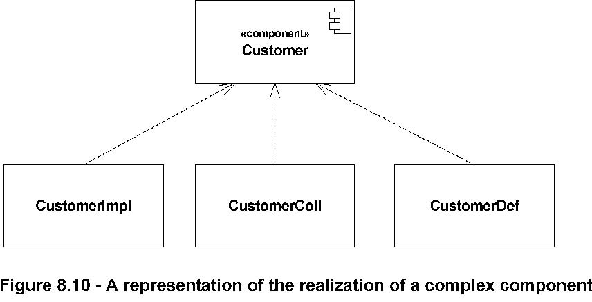 Figure 8.10 - A representation of the realization of a complex component
Alternatively, the internal classifiers that realize the behavior of a component may be displayed nested within the component
shape.
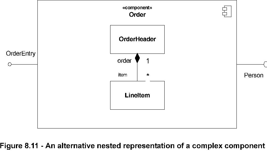 Figure 8.11 - An alternative nested representation of a complex component
If more detail is required of the role or instance level containment of a component, then an internal structure consisting
of parts and connectors can be defined for that component. This allows, for example, explicit part names or connector names
to be shown in situations where the same Classifier (Association) is the type of more than one Part (Connector). That is,
the Classifier is instantiated more than once inside the component, playing different roles in its realization. Optionally,
specific instances (InstanceSpecifications) can also be referred to as in this notation.
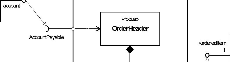
Interfaces that are exposed by a Component and notated on a diagram, either directly or though a port definition, may be inherited
from a supertype component. These interfaces are indicated on the diagram by preceding the name of the
interface by a forward slash. An example of this can be found in Figure 8.14, where /orderedItem is an interface that is
implemented by a supertype of the Product component.
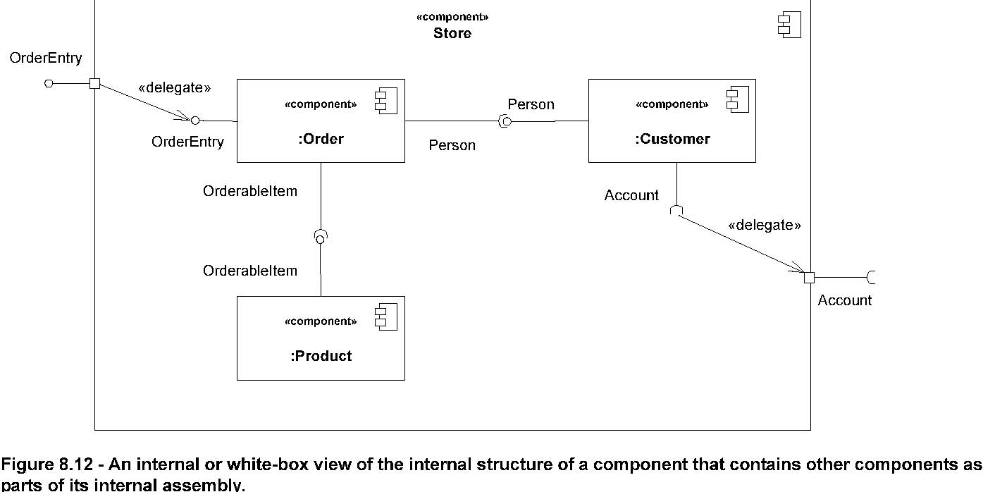 Figure 8.12 - An internal or white-box view of the internal structure of a component that contains other components as parts
of its internal assembly.
Figure 8.12 - An internal or white-box view of the internal structure of a component that contains other components as parts
of its internal assembly.
Artifacts that implement components can be connected to them by physical containment or by an «implement» relationship, which
is an instance of the meta association between Component and Artifact.
*Examples
«component» «component»
Order

Account


«component»
Product
Figure 8.13 - Example of an overview diagram showing components and their general dependencies
«component»
Order
«component»
Account
1
account
AccountPayable «focus»

OrderHeader

/orderedItem 1
«component»
Product
concerns
*
LineItem
OrderableItem
Figure 8.14 - Example of a platform independent model of a component, its provided and required interfaces, and wiring through
dependencies on a structure diagram.
Issue 8105 -Add component icon to :ShoppingCart.
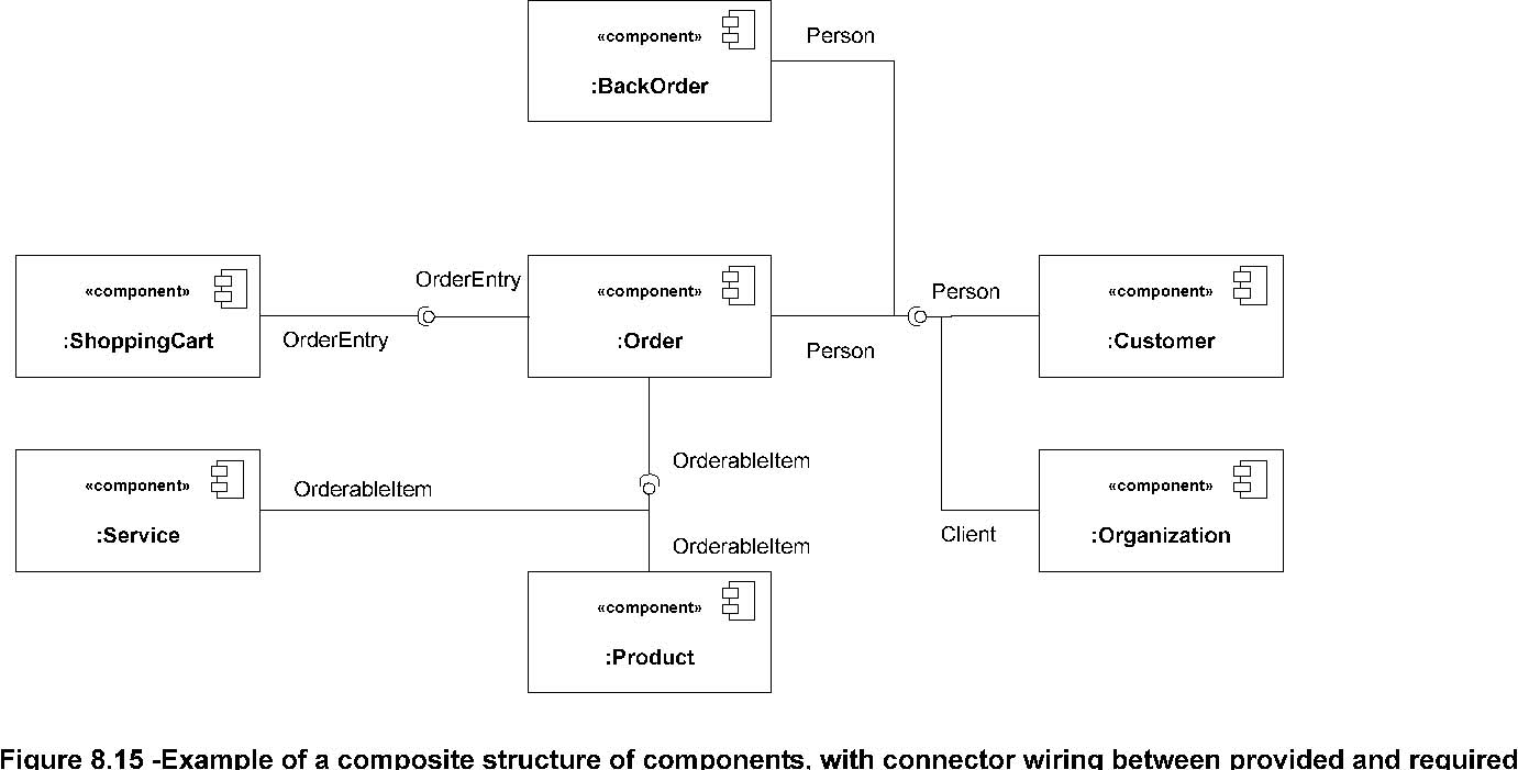 Figure 8.15 -Example of a composite structure of components, with connector wiring between provided and required
interfaces of parts (Note: Client interface is a subtype of Person).
The wiring of components can be represented on structure diagrams by means of classifiers and dependencies between them (Note:
the ball-and-socket notation from
Figure 8.15 may be used as a notation option for dependency based
wiring). On composite structure diagrams, detailed wiring can be performed at the role or instance level by defining parts
and connectors.
*Changes from previous UML
The following changes from UML 1.x have been made.
The component model has made a number of implicit concepts from the UML 1.x model explicit, and made the concept more applicable
throughout the modeling life cycle (rather than the implementation focus of UML 1.x). In particular, the resides relationship
from 1.x relied on namespace aspects to define both namespace aspects as well as ‘residence’ aspects. These two aspects have
been separately modeled in the UML metamodel in 2.0. The basic residence relationship in 1.x maps to the realizingClassifiers
relationship in 2.0. The namespace aspects are defined through the basic namespace aspects of Classifiers in UML 2.0, and
extended in the PackagingComponents metamodel for optional namespace relationships to elements other than classifiers.
In addition, the Component construct gains the capabilities from the general improvements in CompositeStructures (around Parts,
Ports , and Connectors).
In UML 2.0, a Component is notated by a classifier symbol that no longer has two protruding rectangles. These were cumbersome
to draw and did not scale well in all circumstances. Also, they interfered with any interface symbols on the edge of the Component.
Instead, a «component» keyword notation is used in UML 2.0. Optionally, a component icon that is similar to the UML 1.4 icon
can still be used in the upper right-hand corner of the component symbol. For backward compatibility reasons, the UML 1.4
notation with protruding rectangles can still be used.