*Structure diagram
Graphical nodes
The graphic nodes that can be included in structure diagrams are shown in Table 8.1
.
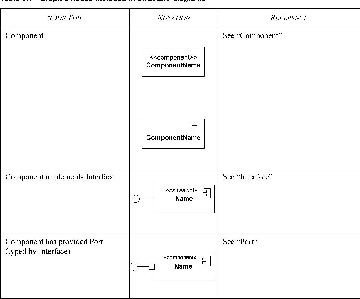
Table 8.1 - Graphic nodes included in structure diagrams
| NODE TYPE | NOTATION REFERENCE | ||||
| Component uses Interface | See Interface Name «component» | ||||
| Component has required Port (typed by Interface) | See Port Name «component» | ||||
| Component has complex Port (typed by provided and required Interfaces ) | See Port Name «component» |
Graphical paths
The graphic paths that can be included in structure diagrams are shown in Table 8.2
.
Table 8.2 - Graphic nodes included in structure diagrams
PATH TYPE |
NOTATION |
REFERENCE |
|||
| Assembly connector |
 |
See assembly connector. Also used as notation option for wiring between interfaces using Dependencies . |