*Generalizations
• V
ertex (from BehaviorStateMachines ) on
page 605
Description
Pseudostates are typically used to connect multiple transitions into more complex state transitions paths. For example, by
combining a transition entering a fork pseudostate with a set of transitions exiting the fork pseudostate, we get a compound
transition that leads to a set of orthogonal target states.
Attributes
Issue 9191 -add default value and remove list
• kind: PseudostateKind Determines the precise type of the Pseudostate. Default value is initial..
Associations
Issue 8409 -correct subsets constraint and ‘state’ entry
• stateMachine : Statemachine [0..1] The StateMachine in which this Pseudostate is defined. This only applies to Pseudostates of the kind entryPoint or exitPoint. {Subsets NamedElement ::namespace}
• state : State [0..1] State that owns the Pseudostate. {Subsets Element::owner}
Constraints
[1] An initial vertex can have at most one outgoing transition.
Issue 8409 -remove redundant ‘(‘
(self.kind = #initial) implies(self.outgoing->size <= 1)
[2] History vertices can have at most one outgoing transition.
((self.kind = #deepHistory) or (self.kind = #shallowHistory)) implies(self.outgoing->size <= 1)
[3] In a complete statemachine, a join vertex must have at least two incoming transitions and exactly one outgoing transition.
Issue 8409 -bold the word ‘and’
(self.kind = #join) implies((self.outgoing->size = 1) and (self.incoming->size >= 2))
[4] All transitions incoming a join vertex must originate in different regions of an orthogonal state.
Issue 8409 -add missing ‘)‘
(self.kind = #join)
impliesself.incoming->forAll (t1, t2 | t1<>t2 implies(self.stateMachine.LCA(t1.source, t2.source).container.isOrthogonal))
[5] In a complete statemachine, a fork vertex must have at least two outgoing transitions and exactly one incoming transition.
(self.kind = #fork) implies
((self.incoming->size = 1) and (self.outgoing->size >= 2))
[6] All transitions outgoing a fork vertex must target states in different regions of an orthogonal state.
Issue 8409 -add missing ‘)‘
(self.kind = #fork)
impliesself.outgoing->forAll (t1, t2 | t1<>t2 implies(self.stateMachine.LCA(t1.target, t2.target).container.isOrthogonal))
[7] In a complete statemachine, a junction vertex must have at least one incoming and one outgoing transition.
(self.kind = #junction) implies
((self.incoming->size >= 1) and (self.outgoing->size >= 1))
[8] In a complete statemachine, a choice vertex must have at least one incoming and one outgoing transition.
(self.kind = #choice) implies
((self.incoming->size >= 1) and (self.outgoing->size >= 1))
Issue 8611 - remove constraints that limit entry and exit points to just top regions 8753 -add new constraint 8968 -duplicate
of 8611
[9] The outgoing transition from an initial vertex may have a behavior, but not a trigger or guard.
(self.kind = PseudostateKind ::initial) implies (self.outgoing.guard->isEmpty() and self.outgoing.trigger->isEmpty())
Semantics
The specific semantics of a Pseudostate depends on the setting of its kind attribute.
Issue 8753 - clarify that the initial transition cannot have a trigger or a guard
• An initial pseudostate represents a default vertex that is the source for a single transition to the default state of a composite state. There can be at most one initial vertex in a region. The outgoing transition from the initial vertex may have a behavior, but not a trigger or guard.
• deepHistory represents the most recent active configuration of the composite state that directly contains this pseudostate (e.g., the state configuration that was active when the composite state was last exited). A composite state can have at most one deep history vertex. At most one transition may originate from the history connector to the default deep history state. This transition is taken in case the composite state had never been active before. Entry actions of states entered on the path to the state represented by a deep history are performed.
• shallowHistory represents the most recent active substate of its containing state (but not the substates of that substate). A composite state can have at most one shallow history vertex. A transition coming into the shallow history vertex is equivalent to a transition coming into the most recent active substate of a state. At most one transition may originate from the history connector to the default shallow history state. This transition is taken in case the composite state had never been active before. Entry actions of states entered on the path to the state represented by a shallow history are performed.
• join vertices serve to merge several transitions emanating from source vertices in different orthogonal regions. The transitions entering a join vertex cannot have guards or triggers.
• fork vertices serve to split an incoming transition into two or more transitions terminating on orthogonal target vertices (i.e., vertices in different regions of a composite state). The segments outgoing from a fork vertex must not have guards or triggers.
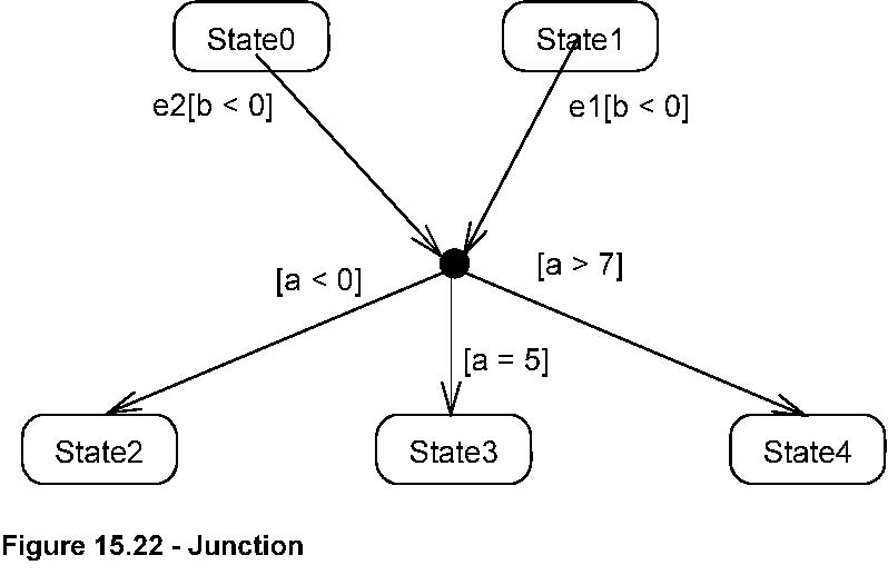
• junction vertices are semantic-free vertices that are used to chain together multiple transitions. They are used to construct compound transition paths between states. For example, a junction can be used to converge multiple incoming transitions into a single outgoing transition representing a shared transition path (this is known as a merge). Conversely, they can be used to split an incoming transition into multiple outgoing transition segments with different guard conditions. This realizes a static conditional branch. (In the latter case, outgoing transitions whose guard conditions evaluate to false are disabled. A predefined guard denoted else may be defined for at most one outgoing transition. This transition is enabled if all the guards labeling the other transitions are false.) Static conditional branches are distinct from dynamic conditional branches that are realized by choice vertices (described below).
• choice vertices which, when reached, result in the dynamic evaluation of the guards of the triggers of its outgoing transitions. This realizes a dynamic conditional branch. It allows splitting of transitions into multiple outgoing paths such that the decision on which path to take may be a function of the results of prior actions performed in the same run-to-completion step. If more than one of the guards evaluates to true, an arbitrary one is selected. If none of the guards evaluates to true, then the model is considered ill-formed. (To avoid this, it is recommended to define one outgoing transition with the predefined else guard for every choice vertex.) Choice vertices should be distinguished from static branch points that are based on junction points (described above).
• An entry point pseudostate is an entry point of a state machine or composite state. In each region of the state machine or composite state it has a single transition to a vertex within the same region.
• An exit point pseudostate is an exit point of a state machine or composite state. Entering an exit point within any region of the composite state or state machine referenced by a submachine state implies the exit of this composite state or submachine state and the triggering of the transition that has this exit point as source in the state machine enclosing the submachine or composite state.
• Entering a terminate pseudostate implies that the execution of this state machine by means of its context object is terminated. The state machine does not exit any states nor does it perform any exit actions other than those associated
with the transition leading to the terminate pseudostate. Entering a terminate pseudostate is equivalent to invoking a DestroyObjectAction .
Notation
An initial pseudostate is shown as a small solid filled circle
(see Figure 15.16
). In a region of a classifierBehavior state machine, the transition from an initial pseudostate may be labeled with the trigger
event that creates the object; otherwise, it must be unlabeled. If it is unlabeled, it represents any transition from the
enclosing state.

Issue 8401 -fix typo Figure 15.16 - Initial Pseudostate
A shallowHistory is indicated by a small circle containing an ‘H’ (see
Figure 15.17
). It applies to the state region that directly encloses it.

Figure 15.17 - Shallow History
A deepHistory is indicated by a small circle containing an ‘H*’
(see Figure 15.18
). It applies to the state region that directly encloses it.

Figure 15.18 - Deep History
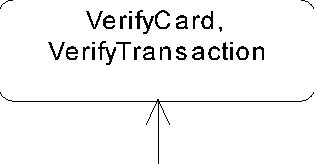
An entry point is shown as a small circle on the border of the state machine diagram or composite state, with the name associated
with it (see
Figure 15.19
).


Figure 15.19 - Entry point
Optionally it may be placed both within the state machine diagram and outside the border of the state machine diagram or composite
state.
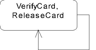
An exit point is shown as a small circle with a cross on the border of the state machine diagram or composite state, with
the name associated with it (see
Figure 15.20
).


Figure 15.20 - Exit point
Optionally it may be placed both within the state machine diagram or composite state and outside the border of the state machine
diagram or composite state.
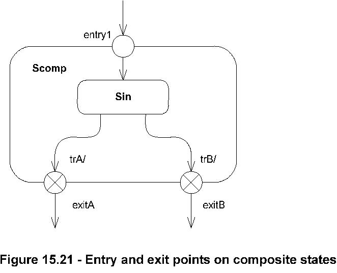
Figure 15.21
illustrates the notation for depicting entry and exit points to composite states (the case of submachine states is illustrated
in the corresponding Notation subsection of
State (from BehaviorStateMachines , ProtocolStateMachines )
on pag
e 571
).
Alternatively, the bracket notation shown in
Figure 15.9
and
Figure 15.10
on page 552 can also be used for the transition-oriented notation.
A junction is represented by a small black circle (see
Figure 15.22
).
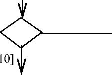
A choice pseudostate is shown as a diamond-shaped symbol as exemplified by
Figure 15.23
.


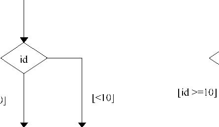
Issue 8401 -fix typo Figure 15.23 - Choice Pseudostate
A terminate pseudostate is shown as a cross,
see Figure 15.24
.

Figure 15.24 - Terminate node
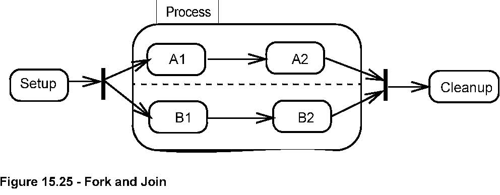
The notation
for a fork and join is a short heavy bar (Figure 15.25). The bar may have one or more arrows
from source states to the bar (when representing a joint). The bar may have one or more arrows from the bar to states (when
representing a fork). A transition string may be shown near the bar.
Process