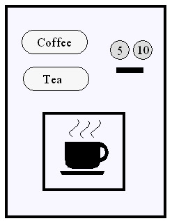
This example is inspired by the Coffee Machine example provided by the documentation about the TAU UML tool. Here is a sketch of the user interface:
| (1) | 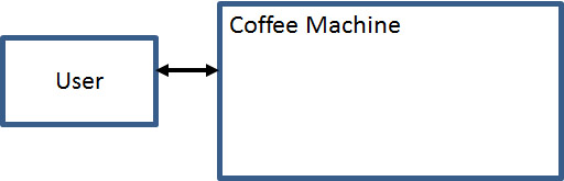 |
The system to be described is the Coffee Machine. This is the simplest architecture: only one interface. |
| (2) | 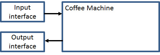 |
As above, but two separate interfaces are considered for input and output. It is assumed that two separate entities in the environment look after input and output, respectively. |
| (3) | 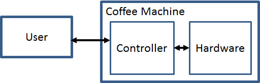 |
As (1) above, but some internal system structure is shown. The user interacts directly with one of the system components. |
Possible interaction sequences:
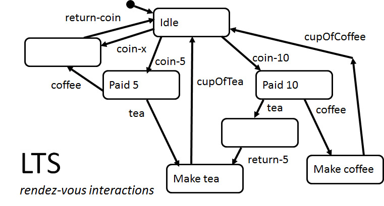
Because of the rendez-vous interactions, at the end of sequence (1), no coin can be entered (the Coffee Machine has no coin transition in its current state (which is paid 5). Similarly, no cupOfCoffee interaction is possible in the initial state.
In the LTSA notation, this state machine can be defined by the following text:
IDLE = (coin[5] -> PAIDFIVE | coin[10] -> PAIDTEN | coinElse -> returnChange -> IDLE),
PAIDFIVE = (tea -> MAKETEA | coffee -> returnChange -> IDLE),
PAIDTEN = (tea -> returnCoin[5] -> MAKETEA | coffee -> MAKECOFFEE),
MAKETEA = (cupOfTea -> IDLE),
MAKECOFFEE = (cupOfCoffee -> IDLE).
The following diagram is produced by LTSA; it is equivalent to the state machine diagram above. Question: To which states of the informal model above correspond the numbered states of the LTSA diagram ?
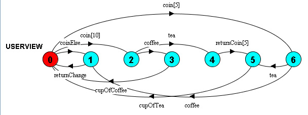
This example is contained in the LTSA-Example "coffee machine - simple". That example also has the check of two properties:
The states and transitions of this model correspond directly to the states and transition of the LTS model above.
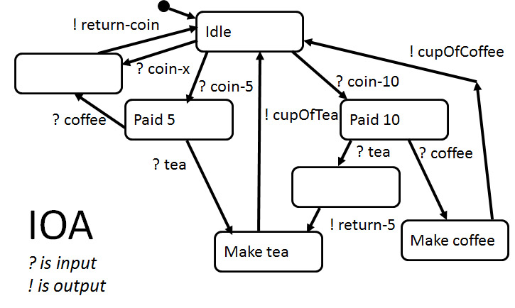
Here a distinction is made between input and output interactions, indicated by ? and !, respectively.
The main difference with LTS modeling is that interactions are not rendez-vous. For instance, an input coin-5 would be possible in the state Paid 10, but the fact that the diagram contains no coin-5 transition from this state means that the hypothesis is made about the behavior of the system environment that the environment will not produce this input when the Coffee Machine is in the Paid 10 state. If this happens nevertheless, we say that this input is a non-specified input.
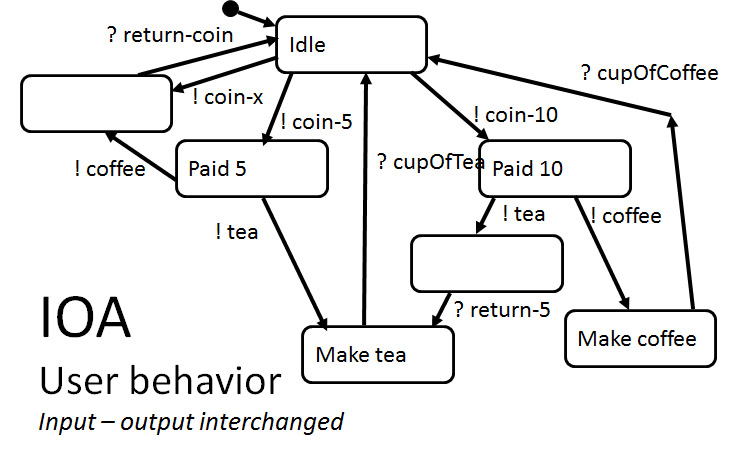
Note that for an IOA model, the corresponding behavior of the environment (the user in our case) can be obtained by the system behavior by interchanging inputs and outputs. See the user behavior on the right side above.
This model is similar to the IOA model, but in the FSM formalism, a transition contains input and output interactions, therefore this model has less states and transitions. For instance, the tea transition from the Paid 10 state contains the tea input event, plus two output interactions, return-5 and cupOfTea. This transition also includes (implicitely) two states that were shown explicitly in the IOA diagram above. Note: Obtaining the user behavior is more difficult for FSM behaviors than explained for IOA behaviors above.
This FSM model can be coded in Umple as a state machine object in the following form (only two transitions are included in the following Umple specification):
| class CoffeeMachine { User user; state { idle { coin(int value) [value == 10] -> paidTen; } paidTen { coffee / {user.cupOfCoffee(new Drink());} -> idle; } } } |
Note that Umple uses the procedure call semantics input events: Each transition is realized as a method that is called when the input event occurs. For instance, the coffee transition from the Paid 10 state (mentioned already above) is translated into the following Java code:
public boolean coffee() { |
There is a problem in this example with the generated code. During the call of the coffee transition by the user object, the method cupOfCoffee is called on the user object - that is, there are two processes executing in the user object simultaneously, the waiting for the return of the coffee method, and the executions of the cupOfCoffee method. This kind of concurrency should be avoided because it is very difficult to understand, in general. The simple system below is another example for this kind of difficulty: What output to the environment would have been produced, and in which state would the machine A be, after an input event a has been processed ? - An implementation of this system will be provided in Lab-3.
Using separate interfaces and agents for input and output as shown in Architecture (2) above avoids this problem. Here is a sketch of the corresponding Umple model. The "Input interface" of the Architecture diagram (2) is represented by the User object, and the "Output interface" is represented by the Delivery object. (Note: only two transitions are included in the behavior of the CoffeeMachine):
|
// This is the CoffeeMachine-2 public class Main { public class Delivery { |
public class User implements Runnable { |
// this is Umple syntax class CoffeeMachine { |
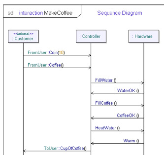
In the architectural model (3), the component Controller interacts with the user (as shown in the above behavior models) and also with the Hardware component which produces the drinks. The LTS model of the Hardware component is shown in the LTS notation below. Each command given to the Hardware is followed by a corresponding response rendez-vous interaction.
HARDWARE = (fillWater -> waterOK -> HARDWARE | heatWater -> warm -> HARDWARE | fillCoffee -> PREPARECOFFEE),
PREPARECOFFEE = (coffeeOK -> HARDWARE).
Using the LTS modeling approach with rendez-vous interactions, the functionality of the Hardware may be used by the Controller component when it is in the Make Coffee state of the LTS behavior model above (we assume that this diagram also models the Controller) - however, in the state Make Coffee, it interacts with the Hardware as shown by the diagram below. Note that we use here the hierarchical state notation of UML for LTS diagrams. A similar diagram defines how tea is made in the Make Tea state of the Controller.
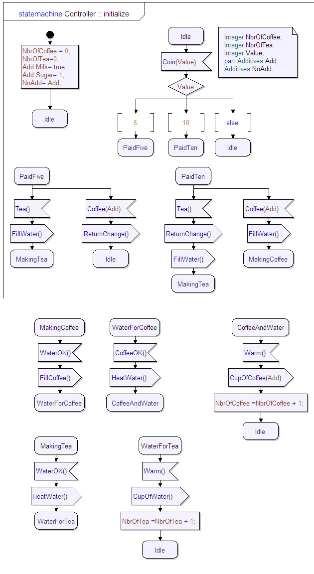
The following is a model of the Controller in LTSA notation. Note: the first three lines of the CONTROLLER definition are the same as above.
IDLE = (coin[5] -> PAIDFIVE | coin[10] -> PAIDTEN | coinElse -> returnChange -> IDLE),
PAIDFIVE = (tea -> MAKETEA | coffee -> returnChange -> IDLE),
PAIDTEN = (tea -> returnCoin[5] -> MAKETEA | coffee -> MAKECOFFEE),
MAKETEA = (fillWater -> waterOK -> heatWater -> warm -> cupOfTea -> IDLE),
MAKECOFFEE = (fillWater -> waterOK -> fillCoffee -> coffeeOK -> heatWater -> warm -> cupOfCoffee -> IDLE).
Note: The intermediate states during the Make Coffee operations are not mentioned in the LTSA notation, only the transition labels are defined.
If we consider that each of these interactions actually has a "direction" (for the Controller, is either input or output), we may represent the sequence of interactions involved in the use case buying coffee by this sequence diagram.
Here is a state diagram of the dynamic behavior of the Controller component in the UML-SDL notation taken from the Telelogic documentation.
The model of the Hardware component given above shows clearly that this entity can receive three commands fillWater, fillCoffee and heatWater which are followed by the respective responses when the requested operation is completed. The commands can be given in any order (assuming that the environment waits that the corresponding response was received). In the LTS modeling approach, it may therefore be more natural to model each command as a single rendez-vous interaction between the Controller and the Hardware - for instance, a signle fillWater interaction, instead of fillWater followed by WaterOK. This can be simply transformed into the object-oriented modeling approach, where the Hardware can be simply modelled as an instance of a class that accepts three methods fillWater, fillCoffee and heatWater.
Using this approach to model the Hardware component, the Controller component may be modeled in Umple as follows (again using two external interfaces for the communication with the user, as in architecture (2)). Note, however, that in Umple, the executed transition methods cannot return any results (only a boolean value indicating whether the transition was executed) - this is OK for this example where no explicit result is returned (only control flow).
| class Controller { Delivery del; Hardware h; state { idle { coin(int value) [value == 10] / -> paidTen; } paidTen { coffee() / { h.fillWater(); h.fillCoffee(); h.heatWater(); del.cupOfCoffee(new Drink()); } -> idle; } } } |