Testing of component-based systems
Introduction
Nature of V&V activities
- vérification :
- to verify that the product satisfies the specified requirements
- "Do we construct the system right ?"
- This means to ensure the process quality
- validation :
- to check that the product will satisfy the needs of the owner and users
- "Do we construct the right system ?"
- This means to ensure the system quality
Methods and techniques
Informal V&V techniques : Reviews (always based on written documents)
- to verify (validate) the results of a phase of the development process
- serves the management team by providing feedback about the status of the project
- provides encouragement for the team to do quality work
- feedback within the team
- the reviewer provides written comments
- the author of the reviewed document answers in written form
Verification (another meaning of this word)
Verifying that the requirements are satisfied. Using methods of formal proofs, or exhausive analysis of all execution scenarios, e.g. by model checking
Testing (Dijkstra said: one cannot proof the absense of bugs, only the presence of bugs - - nevertheless, this approach is very useful in practice.
- The system (or a component) is executed with test inputs and the produced outputs are observed and checked against the requirements.
- Testing tools:
- Test execution environments
- apply different test cases with their test inputs automatically
- generate "log" file including applied inputs and observed outputs (possibly with time stamps and other information)
- may include in the "log" information about values of internal program variables
- Need for an "oracle" : An oracle can decide (automatically) whether the observed outputs are consistent with the requirements (we use the word "requirements" here to stand for the document that is the reference against which the system (or component) is tested). A automatic oracle is often difficult to build; therefore one often includes in the specification of a test case not only the inputs to be applied, but also the possible sets of outputs that are valid responses by the system under test. If no information about the expected output is given, then the (human) tester must make a decision based on the observed outputs (which may be time consuming). Each test is normally written in some language, some times test languages, but often in the same programming language in which the system under test was written.
- In the case that the requirements are non-deterministic, several different sets of outputs may be valid for a given sequence of applied inputs. The system under test should produce one of these sets of outputs. The oracle should verify that this is the case.
- Development of test cases: This is often done "by hand"; some form of automation is possible << G. v. Bochmann and A. Petrenko, Protocol testing: Review of methods and relevance for software testing (invited paper), ACM International Symposium on Software Testing and Analysis (ISSTA'94), Seattle, USA, 1994, pp 109-124 >>
- When have we tested enough ? - This is a difficult question: conflict between the hope of finding all errors and the cost of testing.
- Different categories of tests:
- normal behavior
- behavior in exceptional circumstances (in this category, one often finds more easily programming faults because the programmers and designers pay less attention, or because these behaviors are of more complex nature)
- behavior in case of erroneous inputs
- situations where several inputs arrive at the same time
- Coverage criteria: Ideally, one wants to cover all possible faults (that is, one would like to have, for each possible fault, at least one test case that would discover that fault). However, because of the large number of possible faults, this ideal test coverage is normally not possible to attain. In order to address this (ideal) objective, one has to establish a fault model which defines all possible faults that should be covered by tests (not necessarily all possible faults). For hardware testing, fault models are often used (because one has a good idea what kind of faults normally occur in hardware production). For requirements in the form of state machine behavoirs, there are also well-established fault models (see Section below). However, for software, it is very hard to establish a reasonable fault model; therefore one often establishes instead coverage criteria that are defined independently of a fault model (although fault models are used to justify coverage criteria: for instance, faults of the type where a wrong variable is used in an expression can be discovered by tests satisfying certain dataflow coverage criteria). The following are well-known software coverage criteria. They can be used for white-box testing (the implementation code is the reference) and also for black-box testing (the requirements are the reference - assumed to be given in a high-level programming language form.
- All branches
- All paths (there are often too many, to be practical)
- Data flow criteria, such as all definition-use pairs (that is, all paths including an instance of a definition of a variable in the program and a subsequent use of that variable)
- Choice of parameters:
- typical values (for enumeration type parameters: one test for each possible value)
- limit values (e.g. 1 and 100 for an integer parameter with the range 1 through 100)
- invalid valu
- Some definitions:
- System under Test (SUT): the component that is tested
- Test case: A program that interactions with the SUT in order to check certain properties of the SUT
- The result of a run of a test case is either Pass (successful execution - the property was checked and it is OK), Fail (the property was checked and it is NOT OK), or Inconclusive (the results of the test run are such that one cannot make any conclusions about the tested property). An inconclusive verdict may occur in the case that the SUT has selected an execution path where the tested property cannot be observed.
- Test suite: A set of test cases that are executed independently on the SUT. A test suite is normally designed to cover a certain set of faults.
- A test suite is said to be complete for a given set of faults if the successful execution of all test cases in the test suite proves that none of these faults is present in the SUT.
Black-box testing
In this form of testing, the test cases are selected without the knowledge of the implementation. The test cases are based on the specification (requirements) of the component being tested, also called System under Test (SUT). Black-box testing is sometimes called conformance testing, because it checks the conformance of the implementation with the requirements.
In the case of distributed systems, each component is first tested separately before one does integration testing. One aspect of the specification of the component is the communication protocol to be realized for the interactions with the other system components. The protocol specification is normally written at a relatively abstract level, leaving many details as implementation choices. Therefore, protocol testing is normally black-box testing, where the protocol specification is the reference for the selection of test cases.
Conformance testing in respect requirements in the form of an FSM model
Fault models and implementation assumptions
Output faults only
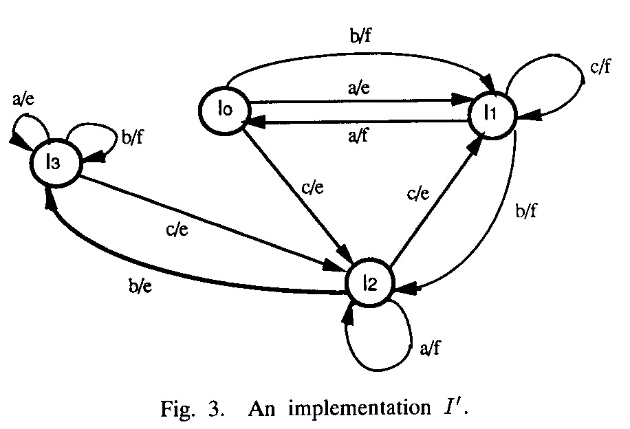
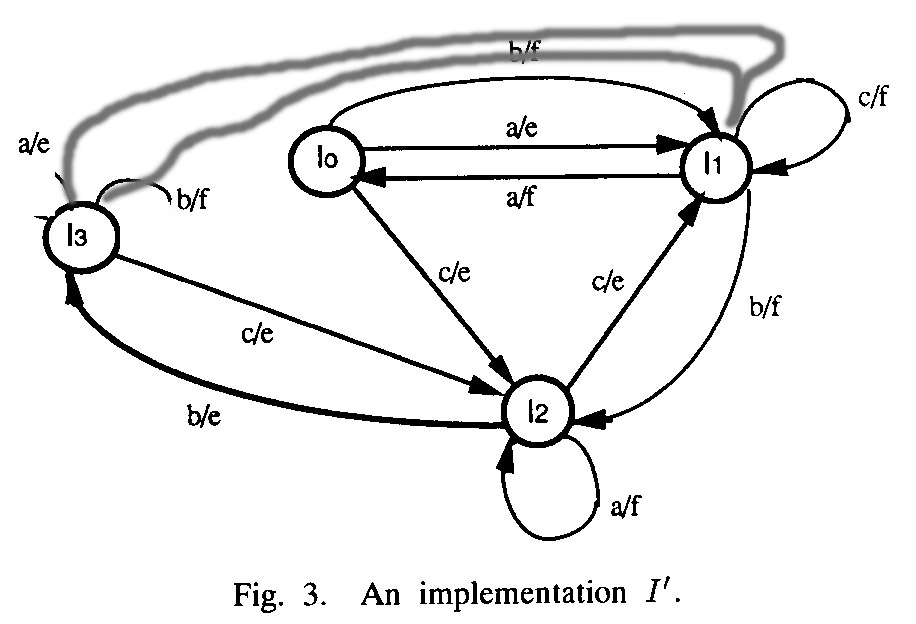
A given transition has an output fault if the implementation of this transition produces a different output than specified by the model. However, it is not so clear what implementation of this transition means. Example from paper on Wp testing method - the implementation of Figure 3 has more states than the specification - the transition with input a from state 1 corresponds to two transitions in that implementation: input a from state I0, and (if S0 is reached by the transition with input from state S2) input a from state I3.
One assumes that (a) the FSM model is minimal, and (b) the implementation has a bounded number of states, normally the same number as the specification (also minimal implementation).
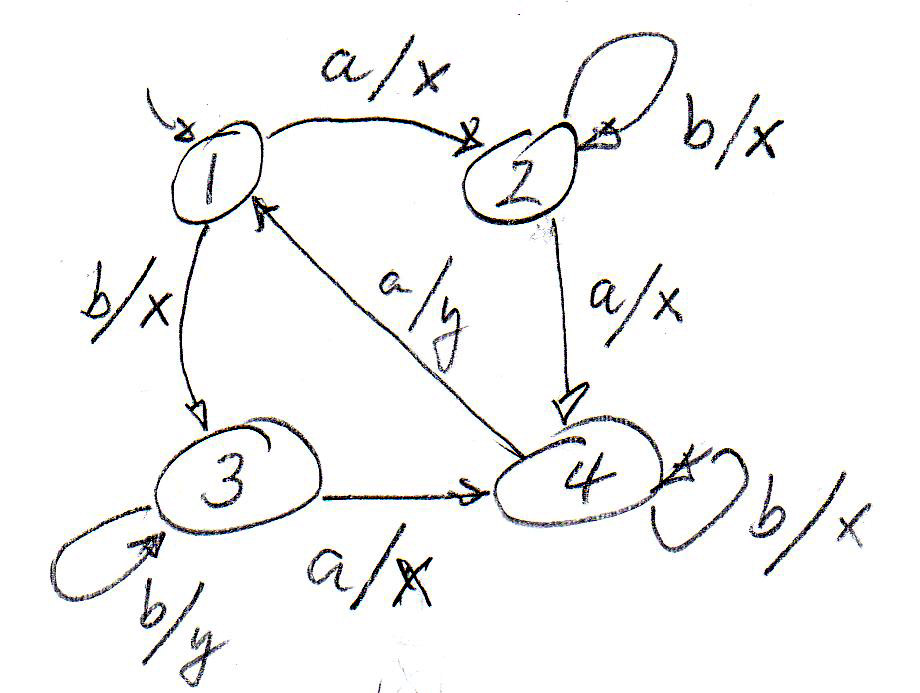
An example of a test case that is complete for output faults: An input sequence that lets the specification go through all transitions (also called Transition Tour). Optimization problem: Find a minimal (with the shortest number of transitions) Transition Tour for a given FSM model. For the simple FSM below, such a test sequence could be ****. It would find any output fault under the assumption that there is no transfer fault (see below). Note: In general, some of the transitions must be executed several times for obtaining a Transition Tour.
Transition faults
A given transition has a transition fault if the implementation of this transition goes to a different next state than specified by the model.
Transition faults are in general much more difficult to check.
- Sometimes, the specification foresees a read-state facility, that is, in each state there is a transition with input Read-State and an output that has as parameter the current state of the machine. In this case, one could simply include a Read-State input after each normal input of the test case.
- In general, the input for an untested transition should be followed by a sequence of inputs such that the provided outputs to these inputs would identify the state which was reached after the first input.
- Distinguishing sequence: This is a sequence which applied to a state of the specification will produce a different output sequence for each state of the specification. If applied after the input of a tested transition, this sequence can be used to determine into which state the tested transition transferred.
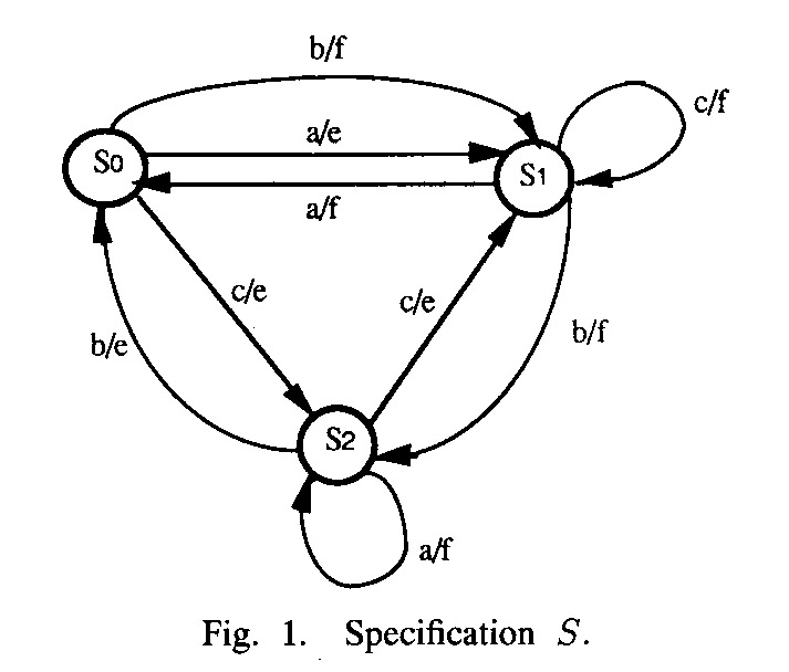
- Unfortunately, such a sequence does not always exist for all FSM models. Example: The FSM of Figure 1 above admits the distinguishing sequence <a, b> which gives the output <e, f> for state S0, <f, f> for state S1, and <ef, e> for state S3,
- W-sequences: This is a set of input sequences, if applied to each state of the specification, give a different set of output sequences for each state of the specification.
The testing has two phases: State identification and transition testing.
- State identification:
- In order to test that the implementation has all the states of the specification, has many test cases for each state. Before each test, a reset is applied to the implementation. It is assume that the reset is correctly implemented, that is, it always leads to the same (initial) state.
- To confirm the presence of a state s in the implementation, one applies each sequence in W to the state s in the implementation (that is, after having applied the input sequence that leads the specification into state s - this sequence is called transfer sequence for state s ).
- Transition testing. The transitions in transfer sequences have already been tested. Now all other transitions are tested as follows:
- For testing transition t, leading from state s to state s', a subset of the W sequences must be applied which distingish state s' from all other states of the specification. Such a subset is called state identification sequences for state s' ( IS(s') ). In the case of the W-method, one uses the whole set W.
- More precisely, there is a test case for each identification sequence. It starts with the transfer sequence to state s, followed by the input for transition t, and then followed by the identification sequence of s'.
- Identification sequence(s): After a tested transition, we know in which state the implementation should be. We could use identification sequence(s) to check that the implementation is indeed in that state. The set of identification sequences is normally different for each state.
During the state identification phase, one still has to use the union of all sets of identification sequences for all states. This union has the property of a W-set. Therefore this phase is not improved. But the transition testing phase may become shorter. There are difrferent kinds of indentification sequences:
- Unique input-output (UIO): For certain FSM models, there is a unique indentification sequence (UIO) for each state.
- Wp method : straightforward approach, which works for all FSM models.
- HIS method: This works also for partially defined FSM models (the other methods assume completely defined models). With this method, IS(s) includes for each different state s' of the specification a sequence for which there is a prefix that can be applied to s and to s' and which provides different outputs for s and s'
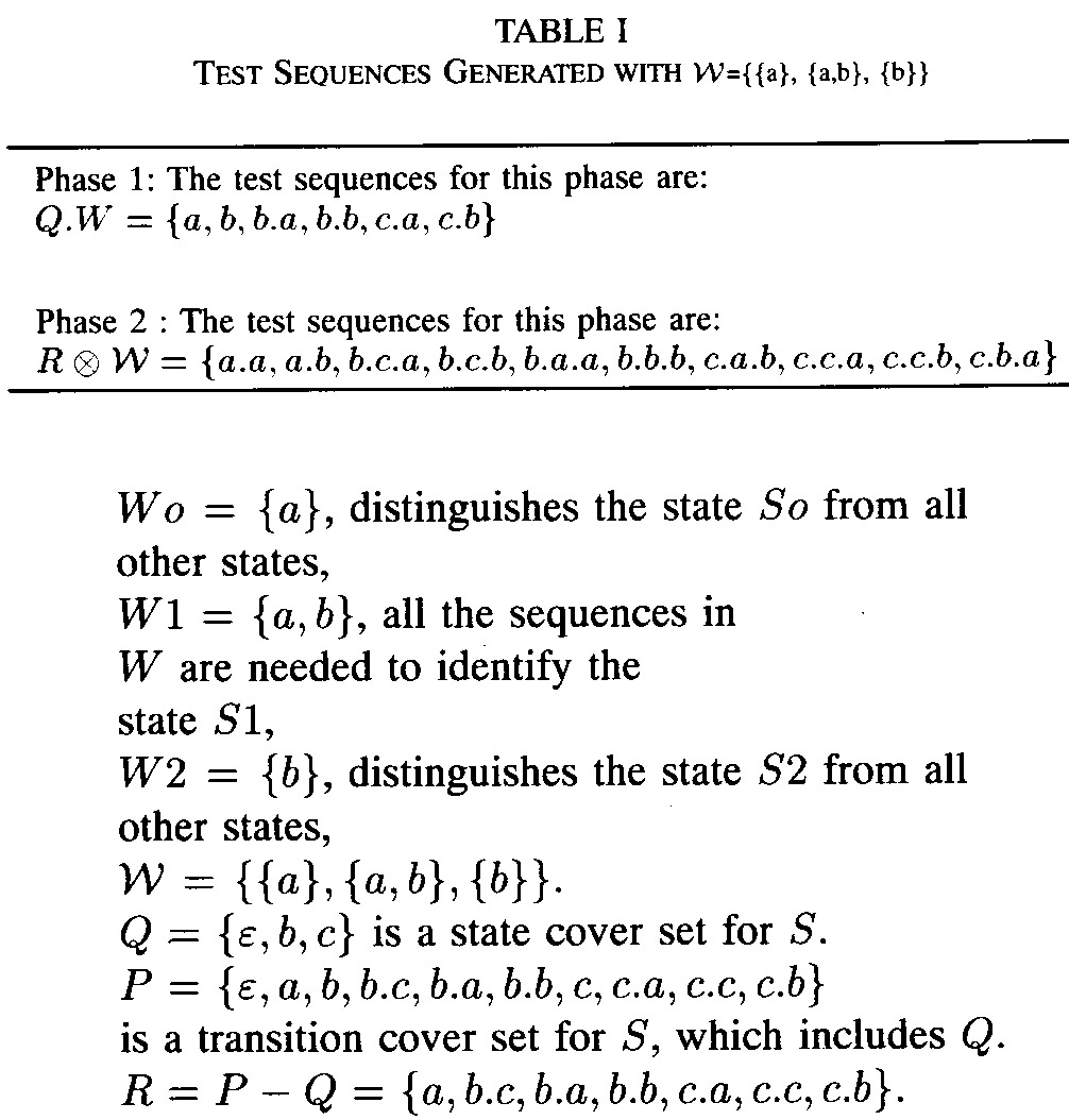
Example: Consider the specification of Figure 1 above. A test suite for the Wp method is given below. Note that for state S1 the IS = {c} may be chosen, which leads to a different test suite. In this case, each state has only a single identification sequence - that is, the UIO method applies. Also note that for this specification, there is a Distinguishing sequence, namely a.b.
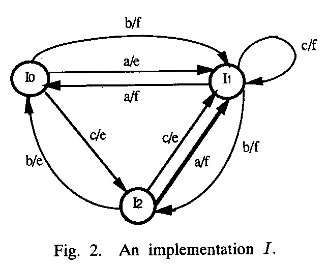
Note: These methods guarantee complete test suites only if one assumes that the implementation has no more states than the specification (which is not satisfied by the example implementation of Figure 3 above). The methods can be extended to cope with a bounded number of additional states in the implementation, but this leads to much longer test cases.- - Example: Consider the modified Figure 3 below. This machine is equivalent to the specification. If a transition from state I3 to state I1 has an output fault, this would not be detected by the above methods (without the extension mentioned).
Conformance testing in respect to extended FSM models
The above FSM testing approaches ignore interaction parameters and additional state variables as found in extended state machine models. Since realistic system specifications often are extended FSM models, it is important to consider testing methods for extended state machine models. The basic idea in this direction is to combine the FSM testing methods (for the pure FSM aspects of the behavior) with testing methods developed for functional (black-box) testing of software systems. In particular, one can apply:
- Different choices of parameters:
typical values,
limit values
- Control flow coverage criteria (all branches or all paths) for the algorithmic part of the actions associated with each transition
- Data flow coverage criteria
for the algorithmic part of the actions and enabling conditions associated with all transitions
Created: November 12, 2014