12.3.44 Pin
*Generalizations
*Description
A pin is an object node for inputs and outputs to actions.
*Attributes
Package CompleteActivities
• isControl : Boolean [1..1] = false Tells whether the pins provide data to the actions, or just controls when it executes
it.
*Associations
No additional associations
*Constraints
See constraints on ObjectFlow .
*Constraints
Package CompleteActivities
[1] Control pins have a control type.
isControl implies isControlType
*Semantics
See
Pin (from BasicActions ) on page 275.
(CompleteActivities ) Control pins always have a control type, so they can be used with control edges. Control pins are ignored
in the constraints that actions place on pins, including matching to behavior parameters for actions that invoke behaviors.
Tokens arriving at control input pins have the same semantics as control arriving at an action, except that control tokens
can queue up in control pins. Tokens are placed on control output pins according to the same semantics as tokens placed on
control edges coming out of actions.
*Notation
Pin rectangles may be notated as small rectangles that are attached to action rectangles. See figure below and examples. The
name of the pin can be displayed near the pin. The name is not restricted, but it often just shows the type of object or data
that flows through the pin. It can also be a full specification of the corresponding behavior parameter for invocation actions,
using the same notation as parameters for behavioral features on classes. The pins may be elided in the notation even though
they are present in the model. Pins that do not correspond to parameters can be labeled as name:type.
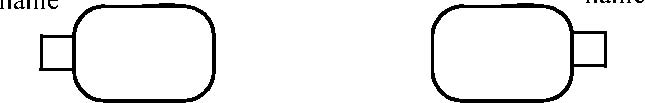
Input pin Output pin
Figure 12.119 - Pin notations
Issue 8859 -add clarifying phrase 9010 -explain about multiple arrows
The situation in which the output pin of one action is connected to the input pin of the same name in another action may
be shown by the optional notations of Figure 12.120. The standalone pin in the notation maps to an output pin and an
input pin and one object flow edge between them in the underlying model. This form should be avoided if the pins are not of
the same type. Multiple arrows coming out of a standalone pin rectangle is an optional notation for multiple edges coming
out of an output pin. These variations in notation assume the UML 2.0 Diagram Interchange specification supports the interchange
of diagram elements and their mapping to model elements, so that the chosen variation is preserved on interchange.
name
name
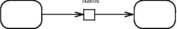
Figure 12.120 - Standalone pin notations
See ObjectNode for other notations applying to pins, with examples for pins below.
Package CompleteActivities
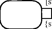
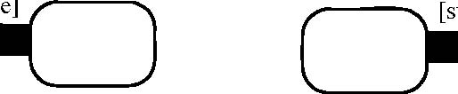
To show streaming, a text annotation is placed near the pin symbol: {stream} or {nonstream}. See figure below. The notation
is the same for a standalone object node. Nonstream is the default where the notation is omitted.
Issue 8263 -fix typo ends instead of end
name
name


[state]

[state]
{stream}
{stream}
{stream}
{stream}
name
Standalone object node, Input pin, Output pin, streaming on both ends streaming streaming
Figure 12.121 - Stream pin notations
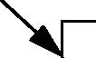
Pins for exception parameters are indicated with a small triangle annotating the source end of the edge that comes out of
the exception pin. The notation is the same even if the notation uses a standalone notation. See figure below.
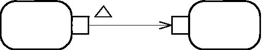
Output pin, pin style, exception
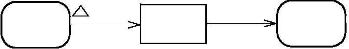
Input and output pin, standalone style, exception
Figure 12.122 - Exception pin notations
Specifying the effect that the behavior of actions has on the objects passed in and out of their parameters can be represented
by placing the effect in braces near the edge leading to or from the pin for the parameter.
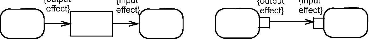
Figure 12.123 - Specifying effect that actions have on objects
Control pins are shown with a text annotation placed near the pin symbol {control}.
See ObjectNode for other notations applying to pins, with examples for pins below.
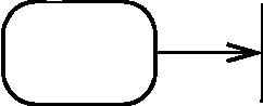
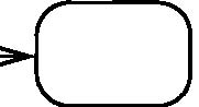
*Presentation Options
When edges are not present to distinguish input and output pins, an optional arrow may be placed inside the pin rectangle,
as shown below. Input pins have the arrow pointing toward the action and output pins have the arrow pointing away from the
action.
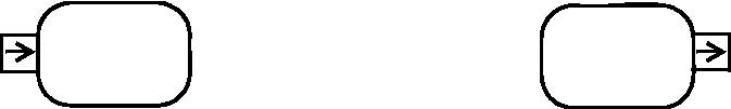
Input pin, Output pin, pin-style, with arrow pin-style, with arrow
Figure 12.124 - Pin notations, with arrows
Package CompleteActivities
Additional emphasis may be added to streaming parameters by using a graphical notation instead of the textual adornment. Object
nodes can be connected with solid arrows containing filled arrowheads to indicate streaming. Pins can be shown as filled rectangles.
When combined with the option above, the arrows are shown as normal arrowheads.
name
name
[state]

[state] name [state]
Input and output pin, Input pin, Output pin,stand-alone style, streaming on both ends pin-style, streaming pin-style, streaming
Figure 12.125 - Stream pin notations, with filled arrows and rectangles
*Examples
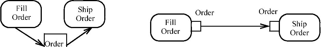
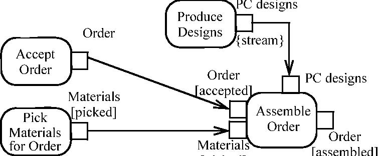
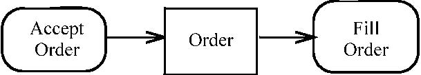
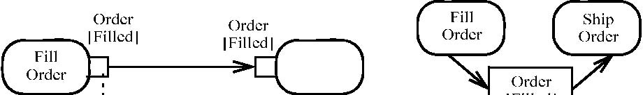
In the example below, the pin named Order represents Order objects. In this example at the upper left, the Fill Order behavior
produces filled orders and Ship Order consumes them and an invocation of Fill Order must complete for Ship Order to begin.
The pin symbols have been elided from the action symbols; both pins are represented by the single box on the arrow. The example
on the upper right shows the same thing with explicit pin symbols on actions. The example at the bottom of the figure illustrates
the use of multiple pins.
[picked]
Figure 12.126 - Pin examples
In the figure below, the object node rectangle Order is linked to a class diagram that further defines the node. The class
diagram shows that filling an order requires order, line item, and the customer’s trim-and-finish requirements. An Order token
is the object flowing between the Accept and Fill activities, but linked to other objects. The activity without the class
diagram provides a simplified view of the process. The link to an associated class diagram is used to show more detail.
Object node
rectangle linked
with a class diagram
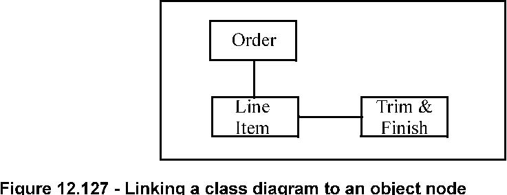 Figure 12.127 - Linking a class diagram to an object node
Package CompleteActivities
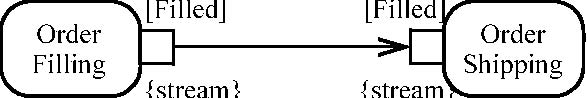
In the example below Order Filling is a continuous behavior that periodically emits (streams out) filled-order objects, without
necessarily concluding as an activity. The Order Shipping behavior is also a continuous behavior that periodically receives
filled-order objects as they are produced. Order Shipping is invoked when the first order arrives and does not terminate,
processing orders as they arrive.

Order Order [Filled] [Filled]

{stream} {stream} {stream} Order {stream}
[Filled]
Figure 12.128 - Pin examples
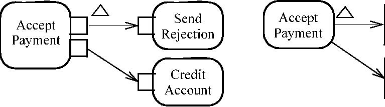
Example of exception notation is shown at the top of the figure below. Accept Payment normally completes with a payment as
being accepted and the account is then credited. However, when something goes wrong in the acceptance process, an exception
can be raised that the payment is not valid, and the payment is rejected.
RejectedPayment
AcceptedPayment
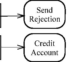
Figure 12.129 - Exception pin examples
The figure below shows two examples of selection behavior. Both examples indicate that orders are to be shipped based or order
priority—and those with the same priority should be filled on a first-in/first-out (FIFO) basis.
[Filled]
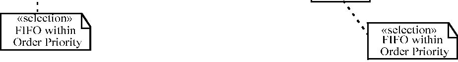

Figure 12.130 - Specifying selection behavior on an ObjectFlow
In the figure below, an example depicts a Place Order activity that creates orders and Fill Order activity that reads these
placed orders for the purpose of filling them.
Order Order
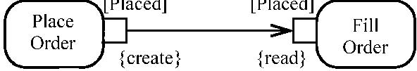
Figure 12.131 Pin example with effects
Pin is specialized in Activities to make it an object node and to give it a notation.
*Changes from previous UML
Pin is new to activity modeling in UML 2.0. It replaces pins from UML 1.5 action model.