| Previous | Table of Contents | Next |
Automation does not support multiple inheritance; therefore, a direct mapping of a CORBA inheritance hierarchy using multiple
inheritance is not possible. This mapping splits such a hierarchy, at the points of multiple inheritance, into multiple singly-inherited
strands.
The mechanism for determining which interfaces appear on which strands is based on a left branch traversal of the inheritance
tree. At points of multiple inheritance, the interface that is first in an ordering of the parent interfaces is included in
what we call the main strand, and other interfaces are assigned to other, secondary strands. (The ordering of parent interfaces
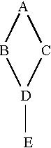
is explained later in this section.) For example, consider the CORBA interface hierarchy, shown in Figure 19-3.
Figure 19-3 A CORBA Interface Hierarchy Using Multiple Inheritance
We read this hierarchy as follows:
• B and C derive from A
• D derives from B and C
• E derives from D
This CORBA hierarchy maps to the following two Automation single inheritance hierarchies, shown in Figure 19-4.
BC

D(+ methods of C)
E
Figure 19-4 The Mapped Automation Hierarchy Splits at the Point of Multiple Inheritance
Consider the multiple inheritance point D, which inherits from B and C. Following the left strand B at this point, our main
strand is A-B-D and our secondary strand is A-C. However, to access all of the object’s methods, a controller would have to
navigate among these disjoint strands via QueryInterface. While such navigation is expected of COM clients and might be an
acceptable requirement of C++ automation controllers, many Automation controller environments do not support such navigation.
To accommodate such controllers, at points of multiple inheritance we aggregate the operations of the secondary strands into
the interface of the main strand. In our example, we add the operations of C to D (A’s operations are not added because they
already exist in the main strand). Thus, D has all the methods of the hierarchy and, more important, an Automation controller
holding a reference to D can access all of the methods of the hierarchy without calling QueryInterface.
In order to have a reliable, deterministic, portable way to determine the inheritance chain at points of multiple inheritance,
an explicit ordering model must be used. Furthermore, to achieve interoperability of virtual function tables for dual interfaces,
a precise model for ordering operations and attributes within an interface must be specified.
Within an interface, attributes should appear after operations and both should be ordered in ascending order based upon the
operation/attribute names. The ordering is based on a byte-by-byte comparison of the ISO-Latin-1 encoding values of the operation
names going from first character to last. For non-readonly attributes, the [propget] method immediately precedes the [propput]
method. This ordering determines the position of the vtable portion of a Dual Interface. At points of multiple inheritance,
the base interfaces should be ordered from left to right in all cases, the ordering is based on ISO Latin-1. Thus, the leftmost
branch at a point of multiple inheritance is the one ordered first among the base classes, not necessarily the one listed
first in the inheritance declaration.
Continuing with the example, the following OMG IDL code expresses a hierarchy conforming to Figure 19-3 on page 19-7.
// OMG IDL module MyModule {
interface A {void aOp1();void zOp1();
interface B: A{void aOp2();void zOp2();
};
interface C: A {void aOp3();void zOp3();
};
interface D: C, B{void aOp4();void zOp4();
}; };
The OMG IDL maps to the following two Automation View hierarchies. Note that the ordering of the base interfaces for D has
been changed based on our ISO Latin-1 alphabetic ordering model and that operations from C are added to interface D.
// ODL// strand 1: A-B-D[odl, dual, uuid(8db15b54-c647-553b-1dc9-6d098ec49328)]interface DIMyModule_A: IDispatch {
HRESULT aOp1([optional,out] VARIANT * excep_OBJ);HRESULT zOp1([optional,out] VARIANT * excep_OBJ);}
[odl, dual, uuid(ef8943b0-cef8-21a5-1dc0-37261e082e51)]
interface DIMyModule_B: DIMyModule_A {HRESULT aOp2([optional,out] VARIANT * excep_OBJ);HRESULT zOp2([optional,out] VARIANT * excep_OBJ);}
[odl, dual, uuid(67528a67-2cfd-e5e3-1de2-d59a444fe593)]
interface DIMyModule_D: DIMyModule_B {// C’s aggregated operationsHRESULT aOp3([optional,out] VARIANT * excep_OBJ);HRESULT zOp3([optional,out] VARIANT * excep_OBJ);// D’s normal operationsHRESULT aOp4([optional,out] VARIANT * excep_OBJ);HRESULT zOp4([optional,out] VARIANT * excep_OBJ);}
// strand 2: A-C[odl, dual, uuid(327885f8-ae9e-19c0-1dd5-d1ea05bcaae5)]interface DIMyModule_C: DIMyModule_A {
HRESULT aOp3([optional,out] VARIANT * excep_OBJ);HRESULT zOp3([optional,out] VARIANT * excep_OBJ);}
Also note that the repeated operations of the aggregated strands are listed before D’s operations. The ordering of these operations
obeys the rules for operations within C and is independent of the ordering within D.