| Previous | Table of Contents | Next |
Viewed at this very high level, Microsoft’s COM and OMG’s CORBA appear quite similar. Roughly speaking, COM interfaces (including
Automation interfaces) are equivalent to CORBA interfaces. In addition, COM interface pointers are very roughly equivalent
to CORBA object references. Assuming that lower-level design details (calling conventions, data types, and so forth) are more
or less semantically isomorphic, a reasonable level of interworking is probably possible between the two systems through straightforward
mappings.
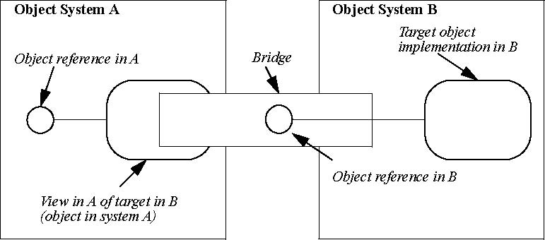
How such interworking can be practically achieved is illustrated in an Interworking
Model, shown in Figure 17-2. It shows how an object in Object System B can be
mapped and represented to a client in Object System A. From now on, this will be called a B/A mapping. For example, mapping
a CORBA object to be visible to a COM client is a CORBA/COM mapping.
Figure 17-2 B/A Interworking Model
On the left is a client in object system A, that wants to send a request to a target object in system B, on the right. We
refer to the entire conceptual entity that provides the mapping as a bridge. The goal is to map and deliver any request from
the client transparently to the target.
To do so, we first provide an object in system A called a View. The View is an object in system A that presents the identity
and interface of the target in system B mapped to the vernacular of system A, and is described as an A View of a B target.
The View exposes an interface, called the View Interface, which is isomorphic to the target’s interface in system B. The methods
of the View Interface convert requests from system A clients into requests on the target’s interface in system B. The View
is a component of the bridge. A bridge may be composed of many Views.
The bridge maps interface and identify forms between different object systems. Conceptually, the bridge holds a reference
in B for the target (although this is not physically required). The bridge must provide a point of rendezvous between A and
B, and may be implemented using any mechanism that permits communication between the two systems (IPC, RPC, network, shared
memory, and so forth) sufficient to preserve all relevant object semantics.
The client treats the View as though it is the real object in system A, and makes the request in the vernacular request form
of system A. The request is translated into the vernacular of object system B, and delivered to the target object. The net
effect is that a request made on an interface in A is transparently delivered to the intended instance in B.
The Interworking Model works in either direction. For example, if system A is COM, and system B is CORBA, then the View is
called the COM View of the CORBA target. The COM View presents the target’s interface to the COM client. Similarly if system
A is CORBA and system B is COM, then the View is called the CORBA View of the COM target. The CORBA View presents the target’s
interface to the CORBA client.
Figure 17-3 shows the interworking mappings discussed in the Interworking chapters.
They represent the following:
• The mapping providing a COM View of a CORBA target
• The mapping providing a CORBA View of a COM target
• The mapping providing an Automation View of a CORBA target
• The mapping providing a CORBA View of an Automation target
a)
b)
c)
d)
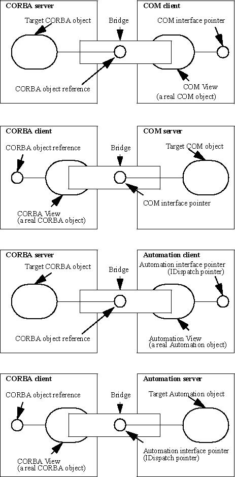
Figure 17-3 Interworking Mapping
Note that the division of the mapping process into these architectural components does not infer any particular design or
implementation strategy. For example, a COM View and its encapsulated CORBA reference could be implemented in COM as a single
component or as a system of communicating components on different hosts.
Likewise,
Figure 17-3 does not define any particular location of the bridge. The bridge
is conceptually between the two object models. The implementation of the bridge may be located on the client or the server
or on an intermediate machine.
The architecture allows for a range of implementation strategies, including, but not limited to generic and interface-specific
mapping.
• Generic Mapping assumes that all interfaces can be mapped through a dynamic mechanism supplied at run-time by a single set of bridge components. This allows automatic access to new interfaces as soon as they are registered with the target system. This approach generally simplifies installation and change management, but may incur the run-time performance penalties normally associated with dynamic mapping.
• Interface-Specific Mapping assumes that separate bridge components are generated for each interface or for a limited set of related interfaces (for example, by a compiler). This approach generally improves performance by “precompiling? request mappings, but may create installation and change management problems.