Next: State models synthesis based Up: State Models Previous: State Models Contents
Control flow based state model generation relies on the implicit flow of control among use case events and the explicit flow of control among use cases as specified by follow lists coupled with enabling directives.
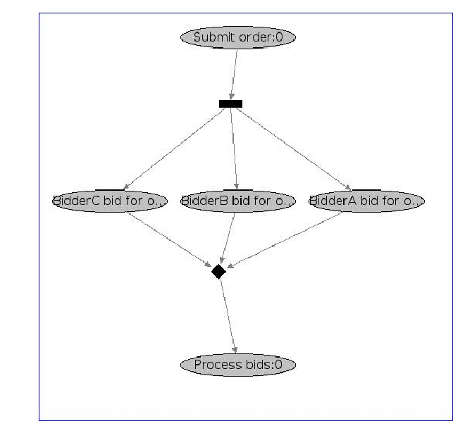
At the use case level, UCEd generates a StateChart-Chart. A UML activity diagram with use cases as nodes. The following is a StateChart-Chart generated by UCEd as shown by the state model viewer.
A StateChart-Chart includes control flow nodes (join, fork, merge, decision) that capture use case sequencing constraints expressed by follow lists and enabling directives.
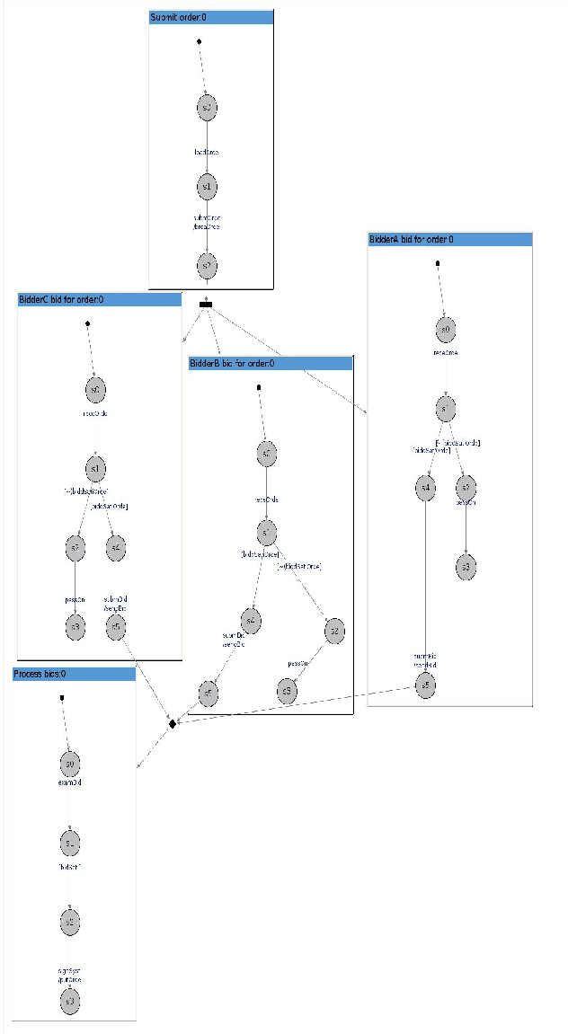
The details of each use case can be shown by double-clicking
on the use case node. Each use case corresponds to a
StateChart. Statecharts are useful for reactive behavior model
description. A
StateChart is defined as a tuple [![]() ,
, ![]() ,
, ![]() ,
,
![]() ,
, ![]() ,
, ![]() ].
].
Any transition starting from a state s also applies to all the sub-states of s.
 |
Stephane 2007-09-03