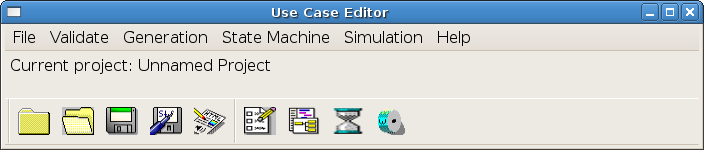
In this tutorial, you will learn how to use UCEd to write a use case, generate domain elements to validate, generate a state model and simulate that use case.
We will use an ATM system as example.
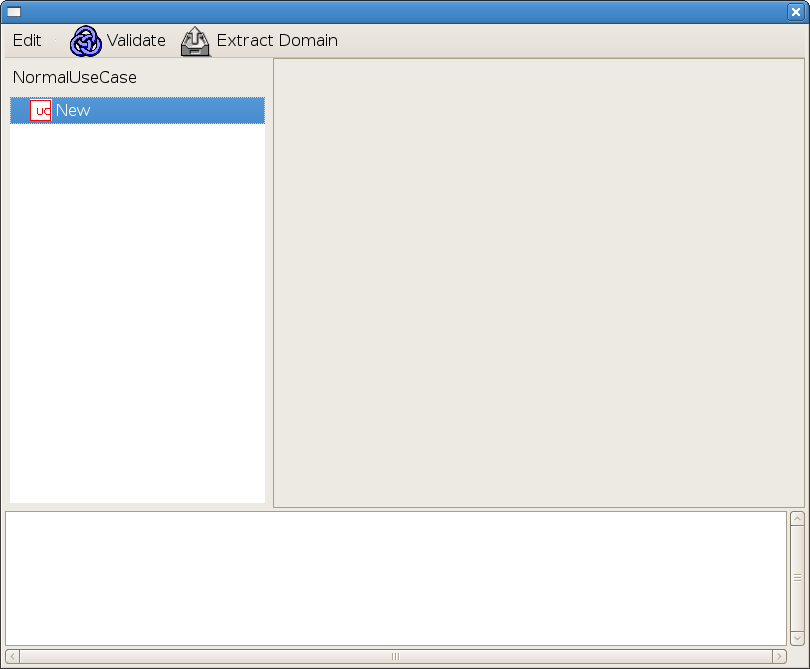
The first task in a use case definition is to come up with a meaningful name. A use case name should capture the high-level goal of the described activity. In this example, we suppose our first use case goal is user's identification and use "Identify User" as a name.
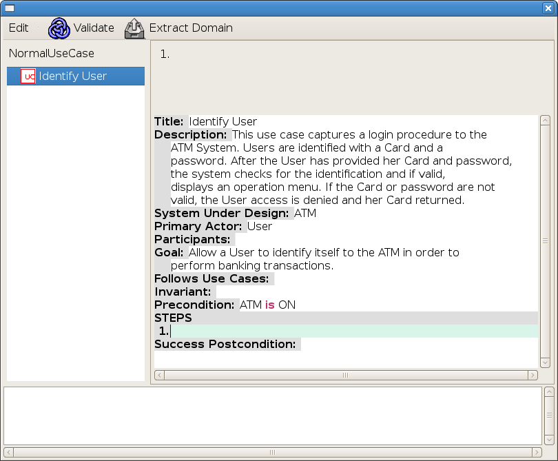
Double-Click on "New" and replace with "Identify User" to specify the new name for the use case by replacing the default name.
Click on the new use case in the use case model tree to open a description editor pane (if not already opened).
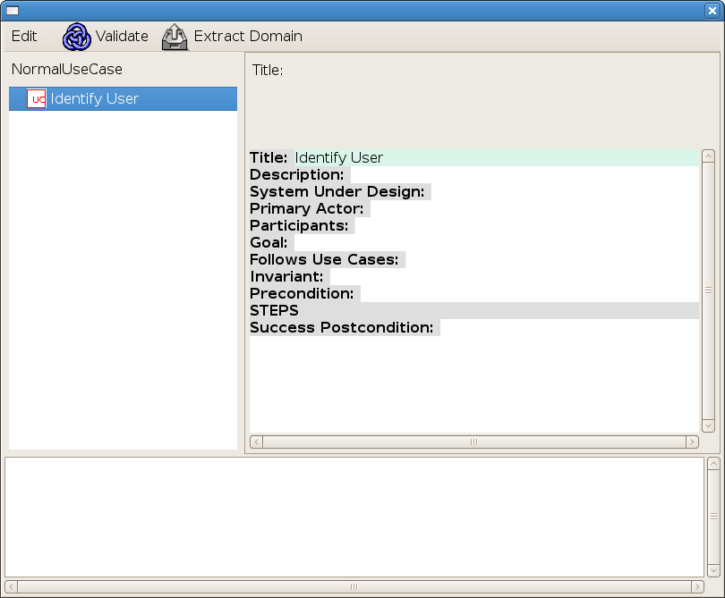
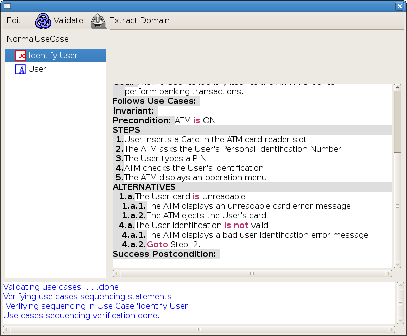
Define the use case description elements. Mandatory elements are: Title, System Under Design, Primary Actor, and Precondition. The title is the same as the use case name.
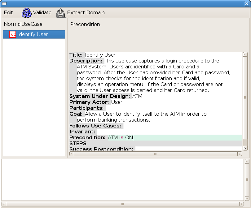
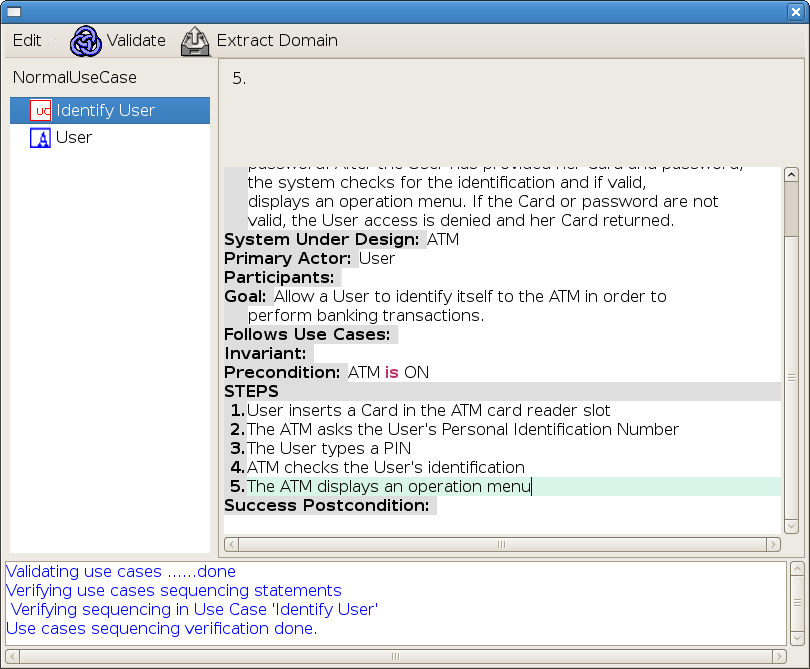
Create a sequence of actor actions, system reactions to fulfill the goal and to realize the postcondition (if already defined).
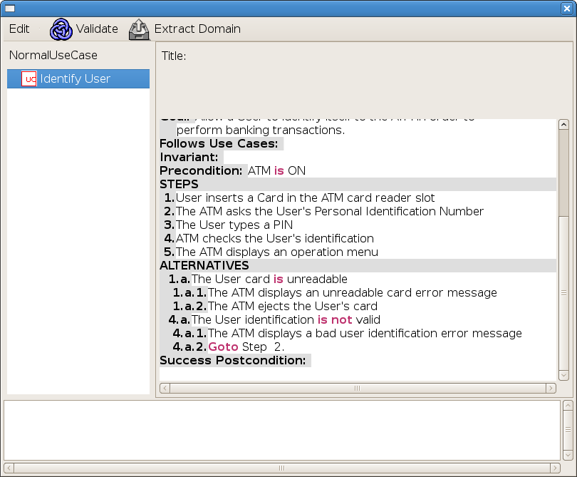
Alternative courses of events may be created by systematically analyzing each step asking questions as
Right-click on a step and select Add Alternative to Step to create an alternative scenario from a step. Note that an alternative to Step X specifies possible execution AFTER Step X is completed.
You can then use ![]() (or File -> Save Project)
to regularly save changes to the project.
(or File -> Save Project)
to regularly save changes to the project.
A domain model is needed for the use case to be parsed.
Double-click on Extract Domain (or select Validate -> Extract Domain From Use Cases), to start a domain model extraction wizard.
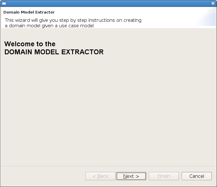
Click on Next to proceed.
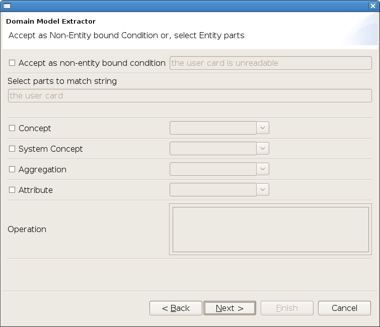
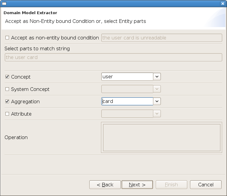
The first sentence being processed is condition "the user card is unreadable". We could accept it as a non-entity bound condition by selecting the top-most box and clicking Next. However, this condition is bound to the domain entity User Card. We can identify the concept from the string "the user card" by selecting user as a domain concept and card as an aggregate of that concept.
In the terminology used:
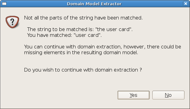
Click Next and respond Yes to the following as determinant "the" is not a domain element.
Repeat the same for all conditions. A similar choice needs to be made for operations. UCEd checks for the verb and makes a suggestion among a list of possibilities.
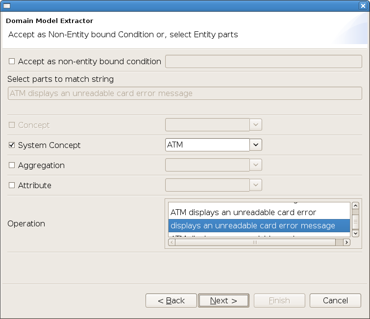
The suggested operation may be accepted or a new operation chosen among the list.
The created domain model is opened by clicking on
icon ![]() (or selecting File -> Open ->
Domain Editor).
(or selecting File -> Open ->
Domain Editor).
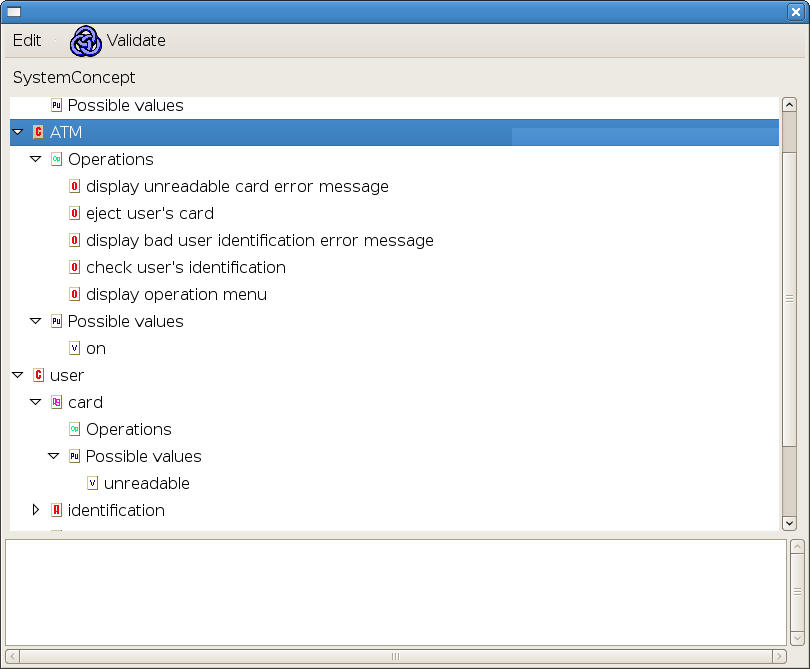
Changes may be made to the domain in the domain editor.
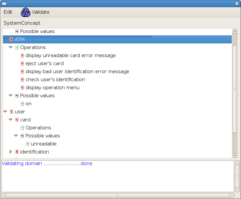
Validate the domain model by clicking on Validate on the domain editor or using (Validate -> Validate Domain).
Once the domain model has been validated, validate the use case by clicking on Validate on the use cases editor or using (Validate -> Validate Use Cases).
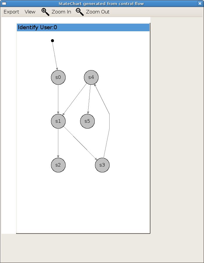
Select View -> Show transition labels to display the labels on the transitions. Move states as needed for visualization.
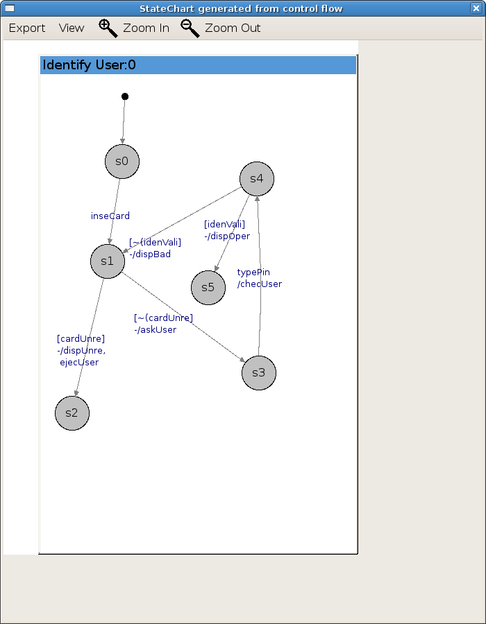
Click on use case "Identify User" in the use case model and select State Machine -> Simulate Use Case Identify User (alternatively use menu option Simulation -> State Machine Obtained from Use Case flow -> Simulate Use Case Identify User).
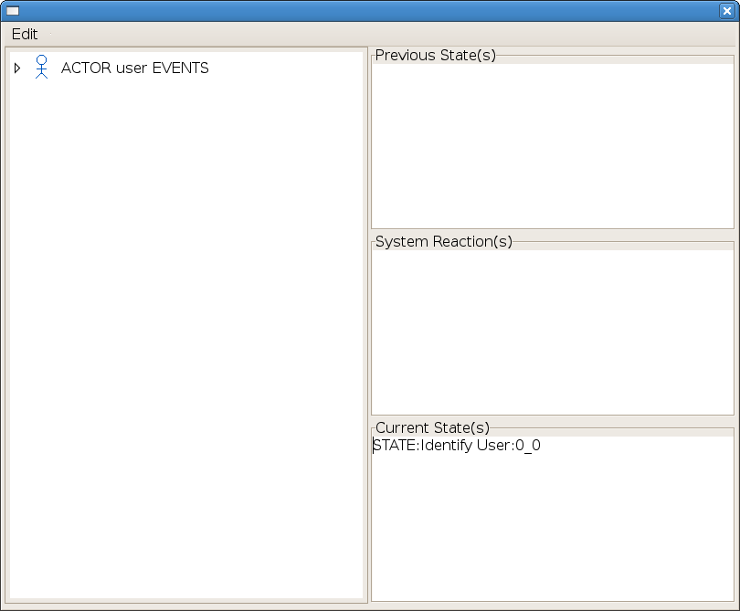
Expand the User's operations.
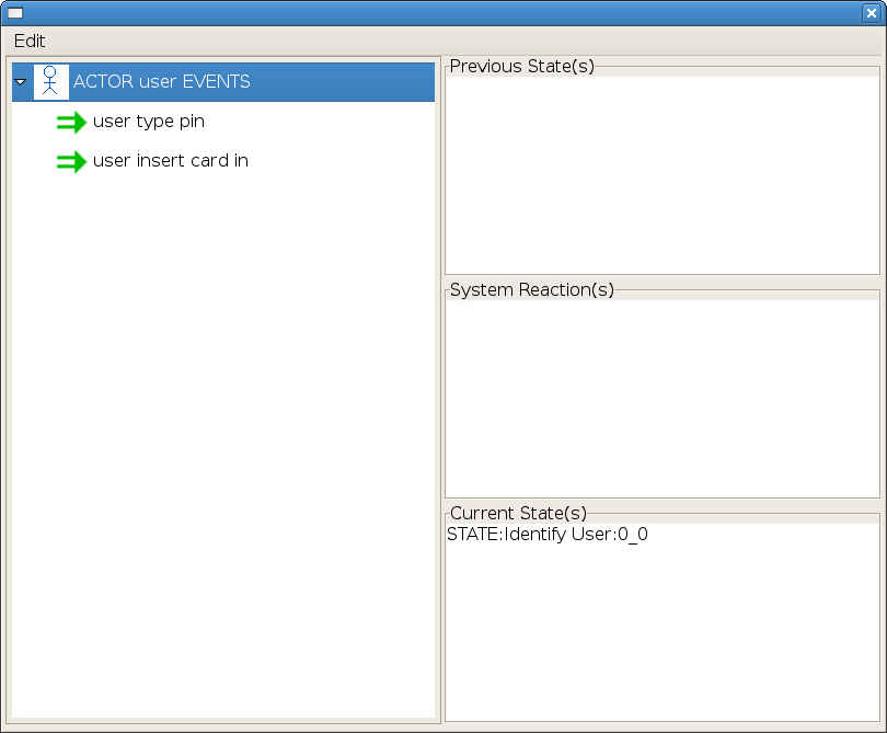
Only one actor (User) has been defined so far and only two operations are defined for that actor. The current state is the state model initial state. Events are simulated by clicking on them in the Actor Events pane. For instance clicking on operation user type pin results in the message.
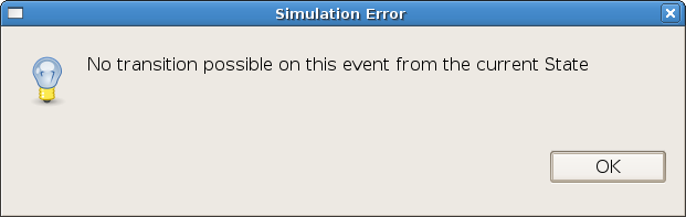
This is normal according to the use case since the first event should be User inserts a card.
When operation user inserts card is selected, the behavior as specified by use case log in depend on whether the inserted card is unreadable or not (alternative 1.a). Accordingly, the simulator asks which possibility should be considered.
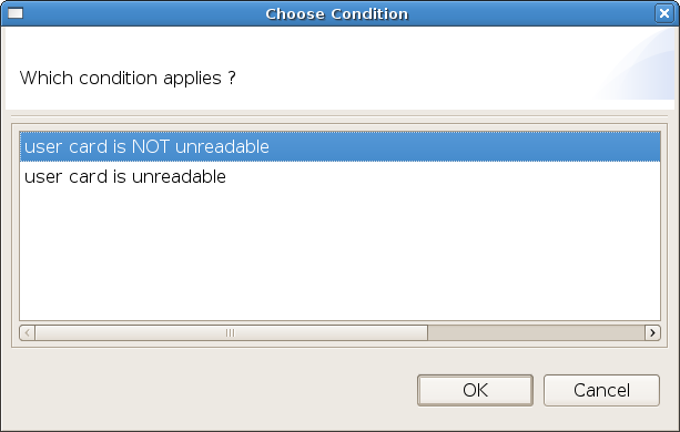
Choosing condition "User card is NOT unreadable" results in
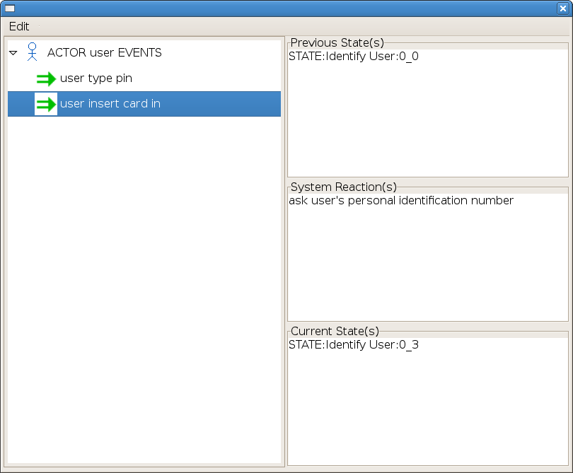
The simulator displays system reaction "ask user's identification number" and is ready to accept the next operation selection.