Behavioral Modeling with States and Transitions
We try to introduce in this chapter the basic concepts of behavioral system modeling, and at the same time introduce some basic modeling paradigms, such as use cases, sequence diagrams, activity diagrams, different kinds of state machines - namely Markov models, Labelled Transition Systems (LTS), Accepting Automata, Input-Output Automata (IOA), Finite State Machines (FSM), and extended state machine models, such as UML State diagrams.
Note that we distinguish in the following between properties that have a "formal" meaning, and other properties that remain informally described (that means they are essentially described in english (or some other natural language) - as a complement to the formal model.
Actions versus States
Choice between state-oriented and action-oriented models - the nature of transitions
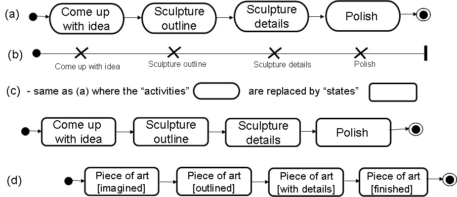
As an example, we consider the process by which an artist creates a wood sculpture (I remember, I did this when I was young): (1) the artist comes up with an idea of a sculpture, (2) s/he takes a piece of wood and prepares an outline of the sculpture, (3) the sculpture is refined in detail, and finally, (4) the sculpture is polished (and can be admired). Here are several representations of this process:
- (a) a UML Activity diagram,
- (b) a Use Case Map (UCM),
- (c) a UML State diagram representing the states of the artist working on the project, and
- (d) a UML State diagram representing the states of the sculpture.
- Notation: The rounded symbols are states or activities, the arrows are transitions. Note that the arrows from the black dot is not really a transition; it simply indicate what the initial state (or activity) of the system is. Similarly, the arrow leading to the black dot with a circle; this arrow indicates what the final state (or activity) is.
Note that diagrams (a), (b) and (c) have exactly the same meaning, while diagram (d) shows the process from another perspective, namely from the point of view of the object that is manipulated. In diagrams (a) through (c), the transitions between the activities/states are short, while some longer time periods are spent during the activities shown in the diagram (or the actions implied by the name of the states - in diagram (c)). In the perspective of the manipulated object (diagram (d)), the transitions take some longer time, while the states represent milestones - identifyable states of the object during the creating process. I would say that the diagrams (a) through (c) are action-oriented models, while diagram (d) is state-oriented. If we compare diagrams (c) and (d), we see that actions become states and states become actions. It is important to note that these two approaches can be used for describing the same reality. Which of these two approaches is better depends on the purpose of modeling.
In other words:
- Diagram (a) is a UML Activity Diagram. Each oval represents an activity, that is, an action. When an action has terminated, the arrow (a "transition") indicates what activity can be next executed. Such a transition is called (in UML) a completion transition - it is executed when the preceeding action is completed.
- Diagram (b) is a Use Case Map. It has the same meaning. A cross represents an activity, which is called "responsibility" in Use Case Maps.
- Diagram (c) is a UML State Diagram. Each rounded rectangular represents a state. In this example, each state represents an activity that is performed by somebody while the system is in that given state. So, this is an example of an "action-oriented" state machine model - each state represents an action, and the arrows represent transition from one action to another - again, these transitions a completion transitions.
- Diagram (d) is also a UML State Diagram. But it is "state-oriented" - each state shown actually represents the state of some object. The object here is the piece of art. The transitions between the states represent some actions that are performed to reach the next state in question. The tranitions here are not completion transitions (except the last leading to the final state) - they represent an action.
- I think that "state orientation" is the normal way of using state machine models.
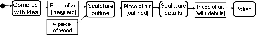
The same reality can also be represented by the UML Activity diagram below including object (data) flow. This diagram includes both views, the action-oriented and the state-oriented one. Here the data objects (represented by the rectangulars) represent the sculpture in its different states. Note: Here the transitions are associated with data objects that are produced by one action and consumed by the next action - they are actually inputs and outputs for these actions, namely the activities in the diagram.
Agents, components and resources
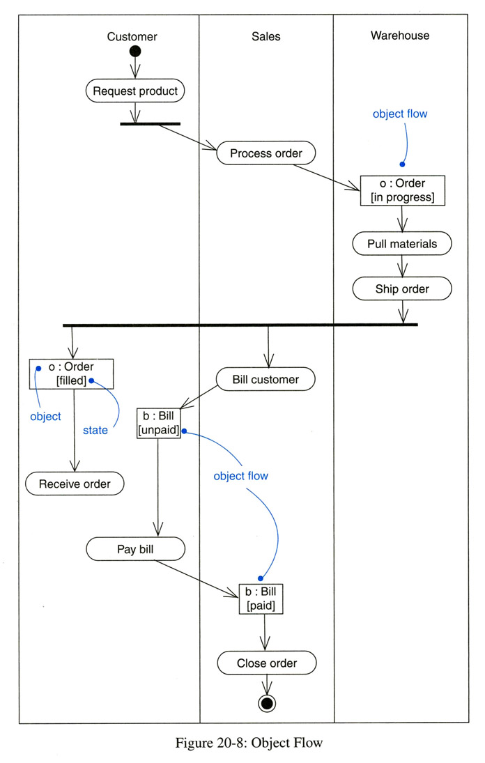
Activity diagrams and UCMs can also be used to define agents. These agents may represent actors, the system, system components or resources that are involved in the identified activities. In UML Activity diagrams, these entities are called "swimlanes", while in UCMs, they are called "components". In practice, these entities often represent actors outside the system boundary, or components that are part of the system. These entities represent resources that are dedicated to a given instance of the Activity diagram, or that are shared between several instances. They are sometimes called "agents" and one may distinguish active and passive agents. For instance, human actors must be considered active agents, also reactive systems that take initiative for performing certain actions. Object instances that provide a method call interface are passive, since they do not take own initiatives. Here is an example of a UML Activity diagram including swimlanes and object flow. (Note: the horizontal thick line at the top of the customer swimlane is probably an error and should be a rectangle reading "o:Order [prepared]").
Here is a short comparison of Activity diagrams and UCMs and the concepts that they allow to specify
Complementary readings
- Markov models: See "Markov chain" in Wikipedia
- UML Activity diagrams: See recommended textbook [Booch] or Wikipedia
- Use Case Maps: See UseCaseMaps.org
- UML State diagrams: See printed course notes from recommended textbook [Booch]
Different semantics for state transition models
Meaning of round symbols
As discussed above, a model represented as a set of state with transitions between these states may have different meaning. (Note: "meaning" is also called "semantics"). In general, each state and each transition has a name to distinguish it from the other entities in the model. As shown by the example above, there are basically two semantics for state transition models:
- Action-oriented semantics (as for the examples (a), (b) and (c) above, and in general for UML Activity Diagrams): The states represent actions performed by some (often non-identified) actor(s). The transitions are normally so-called completion transitions - these are transitions that are spontaneously executed when the specified action is completed.
- State-oriented semantics (as for the example (d) above): The states represent possible states of a particular object - the model represents the behavior of this object. In this case the transitions represents actions, normally performed by the object in question. Sometimes the transitions represent "interactions", that is, actions that are executed jointly by several components within a system, they represent an interaction between one component (the "object" in question) and components in its environment.
- Note: In an state-oriented model where the actions are represented by the transitions, the names of the transitions are evidently very important. Often the names of the states are not so important. In fact, if the names of states change, this does not affect the order in which the actions of transitions could be executed - and often we are mainly interested in the possible orders of execution of these actions.
- Inversely: In the case of action-oriented semantics, where the round symbols represent actions (as for UML Activity diagrams), the name of the round symbols (the activities) are very important, and the states (represented by the arrows between the activities) often have no associated name.
- UML State diagrams support both, state-oriented and action-oriented semantics. In general, state-oriented semantics is assumed (the round symbols represent states). However, by associating a Do-Action with a state, one can specify that in that state the specified Do-Action will be performed.
Triggering of transitions
There are also different semantics concerning the triggering of transitions, that is the question, "under which condition is a transition initiated ? "
- Spontaneous transitions. These are transitions that are initiated spontaneously by the state machine whenever the machine is in a state where the enabling condition of the transition is satisfied.
This kind of semantics corresponds to Dijkstra's Guarded Commands where
each statement is a transition, called guarded comment, which contains an enabling condition (depending on local variables), called the guard, and a command to be executed which normally changes the value of certain variables. A guarded command can only be executed when the guard is true, and at most one command is executed at any time.
- If the enabling condition is satisfied it is in generally not necessary that the transition is initiated immediately.
- If in a given state, there are several spontaneous transitions enabled, the defined behavior is non-deterministic: the specification does not say which of the possible transitions will be initiated.
- In UML, spontaneous transitions are called completion transitions.
- Transitions triggered by an event. The following kinds of events may be considered:
- A message is received from the environment of the state machine.
- The value of a visible variable has changed. This assumes that the transition in question has an enabling condition that depends on this variable, and this condition was not satisfied with the previous variable value, but the new value satisfies the enabling condition.
- The variable in question may be an internal variable of the state machine, and the new value was assigned by a previous transition that was executed.
- The variable in question may be a visible variable in the environment of the state machine. In particular, it may be the variable that represents the state of another state machine in the environment of the former.
- Some time-out period has elapsed. This assumes that there is a timer. A timer can be started by the action of some transition with a given time-out period - after this period, the time produces an event that triggers the (time-out) transition, unless the timer was stopped through the action of some other transition.
Different kinds of interactions with the environment
There are different versions of state-oriented semantics concerning the interactions with the environment. In this course, we mention the following:
- No interactions - only internal transitions. The simple state transition models we consider here identify a certain (finite) number of states for the system. The system state determines the future behavior of the system. Each state has a name, and it is assumed that the state of the system can be determined by some kind of observation. There are also certain transitions between states that are possible, however, these transitions have no "formal" name, although - usually - each transition has some particular "meaning" which remains informal. These transitions do not represent interactions with the environment. Such transition models are often complemented with transition probabilities: such models are called Markov models.
- Rendezvous interactions. Such interactions are used by state machines that are known under the name Labelled Transition Systems (LTS): This is a very simple modeling formalism. There is a finite number of states and a finite number of transitions that are labelled. These labels play the role of transition names, but note that an LTS may have several transitions with the same label. Each label represents a certain interaction of the modeled object with its environment, and the transition diagram defines in which order these interactions may be performed. An example is Figure (b) below, which represents the behavior of a journalist who comes for an interview. The diagram (b) implies that after the action shake hands, the journalist in not able to perform shake hands again.
- Note that the actions of an LTS model abstract from input/output and it is not clear who takes the initiative for performing an interaction, the modeled object or some actor in the environment.
- When the collaboration between several LTS models is considered, and both models include an interaction labelled "xxx", then an interaction "xxx" can only happen when both models have a transition labelled "xxx" from their respective current state. This is why these interactions are called rendezvous interactions (they are jointly initiated by all participating parties - only if they are all ready).
- Distinguishing input and output. The distinction of input and output introduces the important question who initiates an interaction.
- Input to a system component is not decided by the component receiving the input; it cannot determine which is the next input and when would it occur. It may only make certain assumptions about this according to its specification (see specification with assumptions and guarantees).
- If in some given state of the machine, the specification makes the assumption that a message of type X will not be received, then it is not necessary to specify a transition for the reception of X in this state. If during the execution of the system, nevertheless a message X is received in this state, this is called an non-specified reception. The occurrence of such an event indicates that there is a design error in the system: Either the specification should be revised to indicate what to do in the case of the reception of X, or the behavior of the components in the environment should be changed such that the non-specified reception will not occur.
- Note: The detection of non-specified receptions during the design phase of a system is a useful tool for detecting design errors that are otherwise often difficult to identify. Tools, such as LTSA, can be used for this purpose.
- Output of a component is initiated by the component itself (according to the rules - guarantees - laid down by its specification). The production of output may be performed as part of a spontaneous transition, or it may be done in response to some event received.
- There are different kinds of state machines that distinguish input and output:
- Accepting automata: These are state machines that do not produce any output. The inputs that lead to state transitions are provided by the environment, and the purpose of the automata is to tell the environment whether the sequence of inputs that was provided is acceptable according to some given criteria (see more details in the chapter on lexical analysis in this course). For this purpose, each state of the automata is either accepting or non-accepting. When it is in an accepting state, the presented sequence of inputs is acceptable.
- Nondeterministic accepting automata: These automata have some spontaneous transitions that do not consume any input. Their possible execution may lead to nondeterministic behavior (see more details in the chapter on lexical analysis in this course).
- State machine with procedure-call semantics: A number of procedures (methods) are defined for the state machine and each transition is associated with one of these methods. A transition is triggered when the environment calls the associated procedure. The calling process has to wait until the procedure returns (as usual) before doing any other actions. This semantics is one of the semantic variation points of UML State machines and implemented as the "basic" option in the Umple tool.
- Finite State Machines (FSM): These are state machines where a transition is triggered by the reception of an input and may produce an output which is sent to the environment (possibly to component different than the one that triggered the transition), before the model enters the new state defined by the transition. This kind of model is named a Mealy machine, after G.H. Mealy who used this paradigm to model electronic hardware circuits in 1955.
- Note: Another finite state machine model are the Moore machines (not considered in this course): Moore machines are similar to Mealy machine, except that the output produced does not depend on the transition, but is solely determined by the next state that is reached by the transition. This paradigm was used in 1956 by E.F. Moore for the modeling of hardware circuits. This model is quite natural for clocked hardware designs, where the values of each line remains constant between clock pulses. A Moore machine remains in its current state between clock pulses and does a transition during each clock pulse, based on its current state and the value of its input which normally is the output determined by the state of another state machine component. The output of a Moore machine (in a given state) must therefore be considered a constant value (which remains constant as long as the state does not change), and not an event (like in the case of Mealy machines).
- Input-Output Automata (IOA): These are similar to Finite State Machines (Mealy machines), however, each transition is either triggered by an input and does not produce any output, or it is spontaneous transition which produces an output.
- Message passing: For the FSM (Mealy) and IOA models, one usually assumes asynchronous message passing semantics for the transmission of an output from one component which becomes input for another component. The output action of a transition produces a message which will become the trigger for a transition of the destination component. Therefore, each output action must also specify to which component the message should be routed. Normally, one assumes that each transition model has an input queue (with FIFO discipline) where incoming message are stored while the receiving component is busy executing other transitions. Another semantics for message passing is to foresee a pool of received messages for each transition model, where the next message to trigger a transition can be selected depending on the state of the transition model - this is very useful when messages may be received from different parties and it is not predicable in which order they arrive [complementary reading: On the realizability of collaborative services ( H. N. Castejòn, G. v. Bochmann and R. Braek ) Journal of Software and Systems Modeling, Vol. 10 (12 October 2011), pp. 1-21. - PDF ]
Simple examples
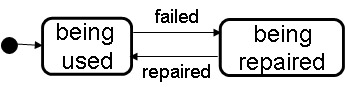
Markov model
The following is an example of a system that may fail and can be repaired. If one adds to each transition a transition rate (probability that the transition will fire within the next time unit if the system is in its starting state), then one obtains a Markov model which allows the prediction of the probability that the system is (at any given time) in a particular state. Example: What is the availability of the system shown above if the transition rate of the "failed" transition is 1/1000 and the rate of "repaired" is 1/100 ?
LTS with rendezvous communication
Here is a very simple example. The model of an interview involving three agents and several actions that are performed in a prescribed order: The collaboration involves three agents, the company director, the journalist, and the secretary. It includes the following actions: a welcome shake hands, interview talk, and a good-bye jointly performed by the director and the journalist; and talk with the secretary, and secretary entering or leaving joinly performed by the director and the secretary (we assume that the director gives the permission for the interruption by the secretary, and indicates when it is time to leave). A reasonable sequencing of these actions is defined by the state diagram (a)), which also represents the order of actions of the company director. Diagrams (b) and (c) describe the behavior of the agent and the secretary, respectively. We note that the interview is interrupted when the secretary enters the room until s/he leaves again.
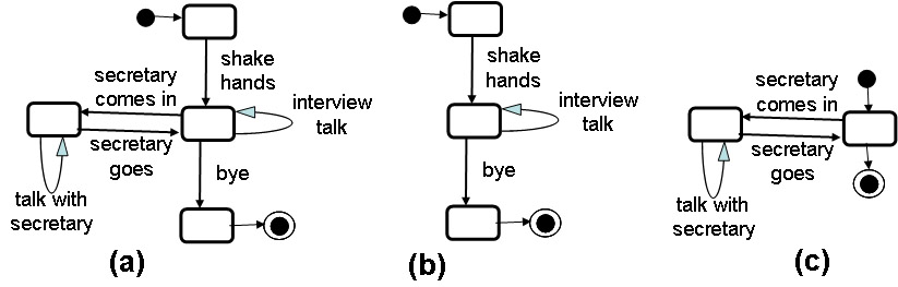
Note: In this example (and when using LTS models, in general), one uses an state-oriented modeling approach where the actions are modeled as transitions, and not as "activities" or "states". In fact, these transitions here represent collaborations between several agents. The LTS transitions may also represent simple interactions between the described system and its environment, as we will discuss below for clent-server system modeling. This approach is similar to diagram (d) of the artist example, although in that diagram the actions are not explicitly mentioned, since the emphasis was on the states of the object.
Semantics of LTS systems: Given an LTS, one is usually interested in all the sequences in which the transitions of the LTS can be executed, starting from the initial state of the LTS and ending in some final state. One calls execution trace the corresponding sequence of transition labels.
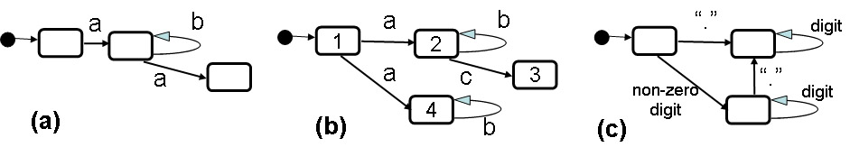
- Sometimes one is interested (only) in all possible traces - this is called trace semantics. For the LTS (a) below, a trace is either empty (that is, it does not include any label - no transition was executed) or it starts with an a; then there may be zero or more b's and then there may be a single a at the end.
- Sometimes one is also interested in the possibility of blocking. For instance, LTS (a) blow blocks for interaction (label) b in the initial state and when two interactions a have occurred in the trace.
- If we have a deterministic LTS (that is one for which one can determine in which state it is if one knows the trace executed so far - like the LTS (a) below) - then the blocking for a given interaction can be deduced from the set of traces: The LTS blocks after a given executed trace for a given interaction x if and only if there is no trace that extends the already executed trace by the interaction x. (discuss proof !).
- See the operations for property verification supported by LTSA: LTSA-example "check properties".
- finding deadlocks
- execution of test sequences
- projection
- property verification by checking trace inclusion
- See the example Coffee machine (the first part on LTS modeling)
- This is not true of non-deterministic LTS. Diagram (b) below shows a non-deterministic LTS (after the trace <a>, it may be in one of two states). This LTS may block after the trace <a, b, b> for the interaction c (if it has gone into state 4), although the LTS also admits the extended trace <a, b, b, c> (by going through state 2). These considerations of possible blockings for non-deterministic LTS is called failure semantics.
Accepting Automata
The ability of a state machine to define a set of acceptable traces is used for the analysis of natural and programming languages. Let us consider an agent with the behavior of the Accepting Automaton (c) shown above (we assume that the upper right state is the only accepting state). This machine accepts as traces any string of characters that represent a valid decimal number without a leading zero. If we combine this machine with a character reader that always offers as input to the machine the next character to be read from an input file, then we obtain a system that has an non-specified reception is the read character string is not a valid decimal number, and if at the end of the input string the automata is in its accepting state, then the input string is valid. This will be further discussed in Section 2 of this course.
Client-server systems
Let us now consider collaboration between an active agent and a passive agent, such as in the case of a client-server system. The server provides an interface that allows the client to call certain methods. Here the client initiates the interactions.
- If these methods can be called in an arbitrary order, as is often the case, then the server may be considered to be always in the same state.
- However, often the internal state of the server determine what kind of results will be returned by a given method call. Consider, for instance, a queue with put and get methods.One may distinguish the states: empty, full, and half-full. The result of the put method will be different in the full state than for the other states.
Combination of input and rendezvous
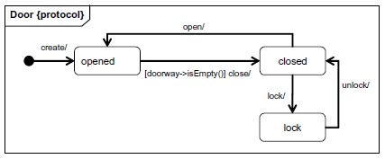
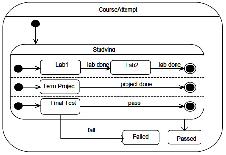
Sometimes, in a client-server model (where it is clear which side initiates the interaction) one has rendezvous semantics for the initiation of the interaction, that is, the passive server may prevent an interaction from happening if it is in a state where this interaction is not possible. For instance, in a coffee machine, the coin insert may be blocked when no coffee is left in the machine, or the coffee buttom could be disabled until enough money is inserted. As an example, we consider a door which can be modeled by the state diagrams below. Clearly, the transition open is not possible in the state lock (the door in this state is blocked for this transition).
- Note: This UML model assumes that this is an FSM where the transitions have no output. With this semantics, the input open in state lock would lead to an non-specified reception. This is clearly not the correct semantics. This is an example of inconsistent semantics in UML examples. UML State machines have a number of semantic variation points, and most authors, unfortunately, simply ignore the resulting difficulties.
Asynchronous Input-Output communication
In asynchronous communication, there is no time instance where both parties are involved in the communication - usually, the sending agent may get involved in other activities while the message propagates to its destination.
- Note, however, that message passing may be used to realize synchronous communication; this is the case for remote procedure calls (RPC) where a message from the caller to the callee indicates the method to be executed and its parameters, and a second message from the callee to the caller delivers the results (if any); in this case the caller will wait for the reception of the second message (which is part of the RPC interaction).
See example of a Coffee Machine.
Different variants of state machines with the same semantics
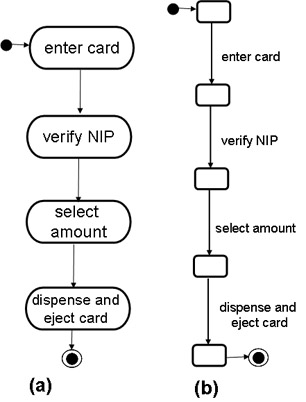
In the following, we show several state machine models for an automated teller machine (ATM). Figures (a) and (b) relatively abstract, they do not explicitly identify the inputs and outputs of for the system. Diagram (a) is a UML Activity diagram and (b) is an LTS.
The other models explicily identify inputs and outputs.
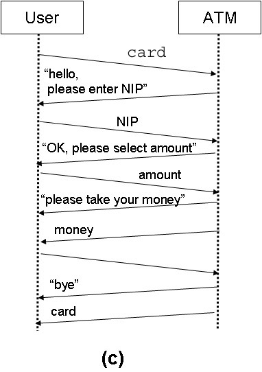
- Figure (c) is not a state machine, but a sequence diagram showing the interactions between the ATM and its environment, the user. defining the behavior of the ATM in terms of message exchange between the ATM and its user. Here each activity of Figure (a) has been replace by an input message from the user and one or two output messages provided by the ATM in response. Many of the output messages are in fact displays of texts presented to the user. This model provides more details than Figures (a) and (b): It shows the initiatives for the different actions (mainly the sending of messages); it also shows more details about the user interface (text displayed during the different steps of the process).
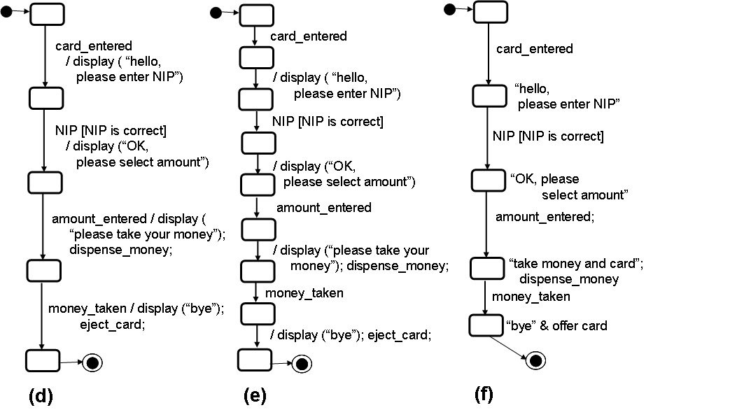
- Based on Figure (c), the UML State machine of Figure (d) has been developed. It is of type FSM with inputs and outputs. It represents the behavior of the ATM and includes the following changes in respect to Figure (c):
- The names of the messages from the user to the ATM have been replaced by events with names that better reflect the nature of the interactions with the user. E.g."card" message has been replaced by the event "card_entered".
- The second transition includes a condition that is assumed to be valid for the subsequent behavior; written "[NIP is correct]".
- Some of the message sending operations have been replaced by the name of local actions that better reflect the nature of these interactions with the user. E.g. the sending of the "money" message is replace by calling the local procedure "dispense_money()".
- Diagram (e) represents the same behavior as diagram (d) - it is given in the form of an IOA (each transition has either a single input or a single output interaction). The output transitions are spontaneous.
- Diagram (f) shows the same behavior in the form of a Moore machine (output is associated with the state of the machine, not with a transition).
Extended state machine models
The formal models of FSM or IOA are characterized by a finite set of possible inputs, a finite set of possible outputs, and a finite number of state, as well as an initial state and the transition function (as discussed above). For most modeling tasks, such formal models are too restrictive. For instance, in the example of the ATM shown above, one has already introduced certain extensions: there are a large number of possible NIP values. In the formal FSM model, one would either have to ignore these different values, or introduce a separate NIP-message for each possible NIP value. One also assumes that there is a way to determine whether the NIP is OK or not. What about modeling the fact that the card is not returned in case that 3 wrong NIP values were provided ?
In the examples above, these extensions were informally modeled by using some names and/or comments that suggest certain properties. However, it would be better to formalize these aspects. For this purpose, state machine modeling paradigms are often extended by introducing the following formal concepts:
- Input and output interactions may have parameters. These parameters are declared in the definition of the interface, and their data type is indicated.
- A state machine instance may have state variables (in addition to the implicit "STATE" variable that stores the current state of the machine). These variables are declared as local variables. In UML, the attributes of the Class defining the state machine may be used for this purpose.
- Each transition is associated with an enabling condition that must be true for the transition to be executed. In general, this condition may depend on the state variables of the machine instance and the values of the input parameters. The absense of an explicit condition means that the condition is True.
- Each transition is associated with an action which is executed when the transition is performed, sometimes called "effect". This action may be a complex algorithm (as in the case of Umple or the SDL language). In any case, the action normally includes: (a) the execution of assignment statements that update certain state variables, and (b) the preparation of certain output messages including the expression defining the values of output parameters. These actions may depend on the current values of the state variables and the values of the input parameters.
Example: extended state machine model of an ATM
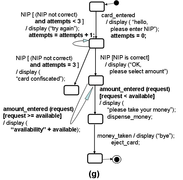
Below is the example of an ATM model that includes some more formal specification of properties using the extended formalism described above, using the notation of UML State diagrams. It is assumed here that the machine has two state variables:
- an integer available representing the number of cents available in the account of the user, and
- an integer attempts representing the count of wrong NIP values submitted.
It is also assumed that the input amount_entered contains an integer parameter, called request, representing the number of cents the user wants to withdraw, and that the output display contains a String parameter which contains the text to be displayed to the user. The elements refering to these variables or interactions, in the following state machine model, are written in bold. The notation for writing the enabling conditions and expressions for assignments or output parameters is usually borrowed from the language that is used by the UML tool for the generation of executable code (in order to simplify this generation process). In the example below, we have used Java syntax.
Features of UML Activity diagrams and State diagrams
Several languages for modeling state machines, based on the above concepts, have been developed, and some have been standardized. CASE tools have been developed for several of these languages. They help in editing models, allow simulated execution and the generation of corresponding sequence diagrams (for the verification and validation of the specification) and for automatic generation of code which provides an implementation of the model or can be integrated with other software components. We mention in particular the following languages:
- UML Activity diagrams. The main features of Activity diagrams are discussed in Al Osman's slides together with some examples.
The semantics of Activity diagrams underlies certain other specification languages for workflow and process modeling, such
BPMN
(Business Process Modeling Notation)
- Note: This is not part of the course topics.
- SDL: This is a graphical language that has been developed and standardized since the early 1970ies. Recently, features of this language have been included in UML-2 and SDL has become a profile of UML. It contains some interesting features, such as symbols for input and output (see example), and a notation for sub-component structures. Some very interesting verification tools were provided by the Telelogic company (which was bought by IBM some years ago).
- Note: This is not part of the course topics.
- UML State diagrams: This notation includes many features (too many ??), in addition to those shown in our simple examples above. It can be used for presenting models that are an FSM, an IOA, or a Moore machine. The following gives an overview of some of the features:
- The generation of output messages is just a special case of "actions". Action also include calling local procedures or performing assignment statements on local state variables.
- Actions can be associated with transitions (as in Mealy machines). There may also be actions associated with entering a state (so-called "entry" action) or with exiting a state (so-called "exit" action). In addition, a "do" action may be specified which will be executed while the system is in that state. In general, when a transition is fired (only if its enabling condition is satisfied), first the exit action of the current state is executed, then the transition action is executed and then the entry action of the next state (and the "do" action if it exists).
- Note: In the example (c) at the beginning of these notes, the names of the states actually represent "do actions". By the way, this example shows the similarity of Activity diagrams and UML State diagrams: The activities of an Activity diagram may be rewritten as states of a State diagram with "do actions" equal to the activity names. However, in the presence of concurrent activities, the correspondence does not always work out because the concurrency in State diagrams is more restrictive than in Activity diagrams.
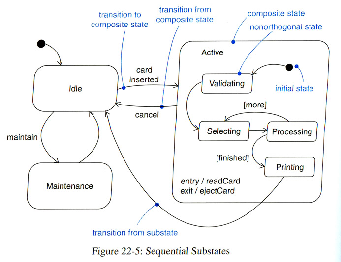
- A state may be hierarchically structured into sub-states, a concept introduced by Harel's State Charts, also called hierarchical state machines. The notation of hierarchical states allows certain abbreviations:
- A transition leaving the hierarchical state has the meaning that the triggering event of this transition will lead to the execution of this transition from each of the sub-states of the hierarchical state.
- One may define a so-called "history state" (H) within a hierarchical state. A transition leading to the history state will actually lead to the sub-state of the hierarchical state which was the last sub-state that was active. For instance, a transition on event e leaving the hierarchical state and entering the history state is equivalent to one loop-back transition on event e from each sub-state.
- The sub-states of a state may be partitioned into several concurrent sub-machines. These sub-machines are active concurrently and normally involve different input and output interactions. The different concurrent sub-machines are assumed to evolve independently of one another.
Complementary readings
Real-time modeling
The modeling paradigms discussed above (except for the Markov models) only describe the order in which the different interactions at the different interfaces may occur during the execution of the system. In many cases, there are also performance requirements that must be met:
- statistical performance properties: these are statements that say that some delay between two events should, on average, be equal to, smaller than, or larger than some specified time duration. Often one may also state properties of the random distribution of the delay, for instance, that the delay should be in 95% of the cases be smaller than some specified value.
- hard real-time performance properties: these are statements that say that some delay between two events should always be equal to, smaller than, or larger than some specified time duration.
If the requirements of a system include statistical or hard real-time performance properties, one says that the system is a real-time system. Most of the time, these systems are reactive systems (see above).
Modeling paradigm (a): a real-time variable NOW
In many situations, a variable representing the current real-time is available (e.g. provided by the operating system), often called "now". The time of a modeled event may recorded by copying now into a local variable. Then a later transition of the model may include an enabling condition which states the the current real-time (e.g. now) should be equal to the stored time value plus some given delay duration.
Modeling paradigm (b): Timed automata
The formal model of Timed Automata (that is, timed state machines) considers that a state machine is associated with a certain number of clocks that are always running. A clock may be reset to zero by a transition (in order to show, in the future, the time that has passed since that transition). Then other transitions may include enabling conditions that specify some constraints for one or several clocks, each constraint requiring that the clock value be within a given range of values. Many CASE tools have been developed for this kind of modeling paradigm. (Not further discussed in this course).
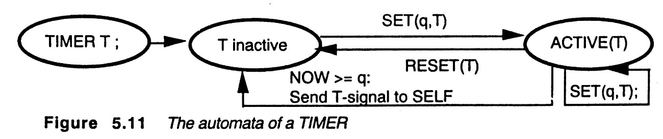
Modeling paradigm (c): Timers and time-outs
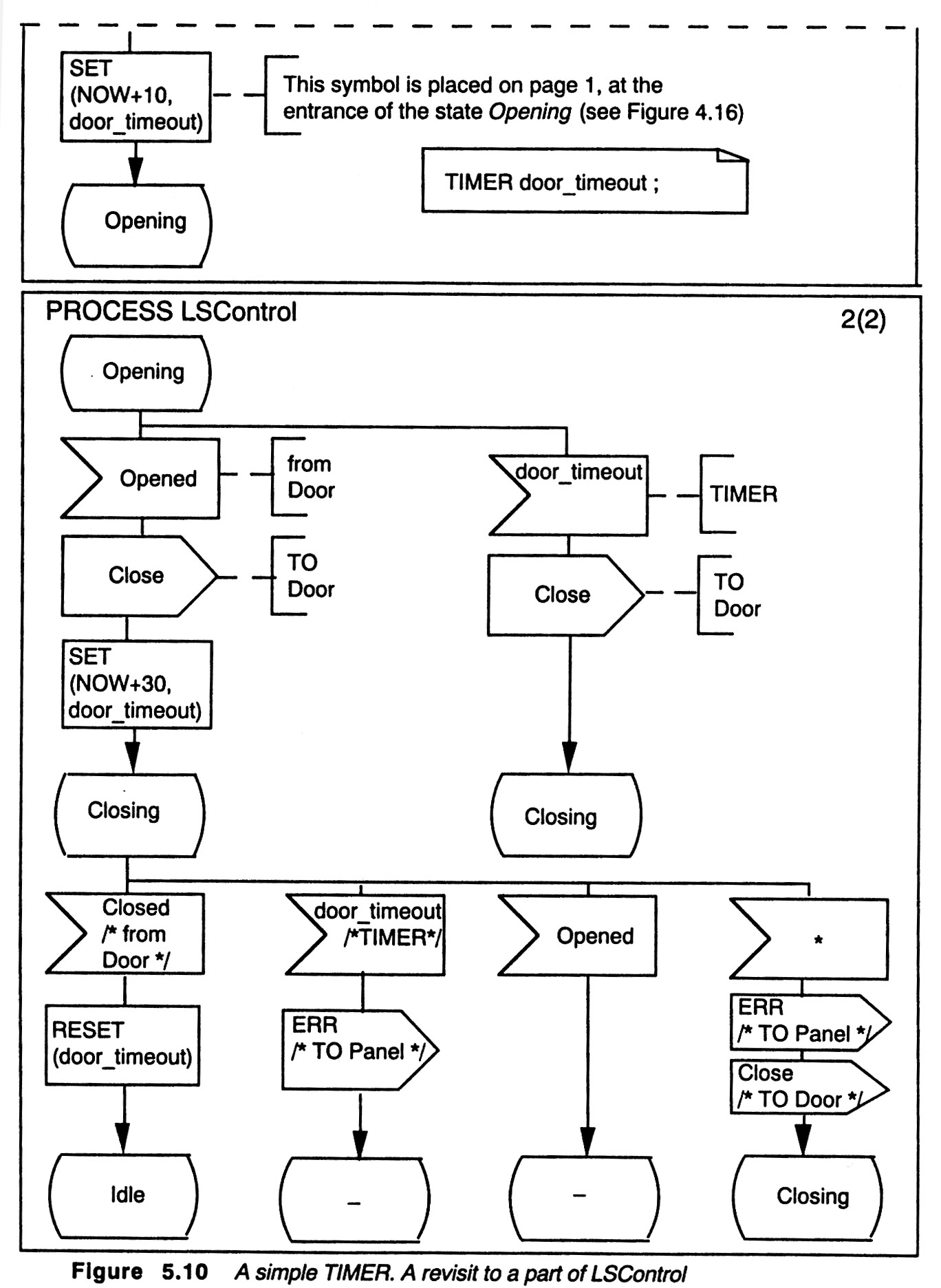
SDL has adopted the modeling approach by which a state machine may be associated with a certain number of timers (appearently this is not supported by normal UML). Timers are clocks that normally do not run (in the inactive state), but they can be set to start running until they reach a given time value, at which point they will generated a so-called "time-out" and stop running. They may also be reset to go back to the idle state before the time-out is reached. The occurrence of a time-out is handled by the state machine as an event. Therefore the specification of the machine should include appropriate transitions for the cases that some of its times produces a time-out. Here is a state diagram of a timer:
The following is an example of a behavior presented in the SDL dialect of UML (called transition-oriented notation). It includes on timer called door_timeout which is set before the system enters the Opening state. A time-out occurs if the Opened signal is not received after 10 time units. If the Opened signal is received before that time, the timer is set again to a new value and a time-out will occur if the Closed signal is not received within 30 time units.
Course notes - Gregor v. Bochmann - University of Ottawa. Created January 2011, last update: January 13,
2015