Here is an informal sketch of a state diagram defining the user perspective. It shows that the user has to enter a coin before s/he can choose between a tea or a coffee.
The following is an equivalent state diagram obtained automatically by the LTSA tool from a more detailed TLS model given below:
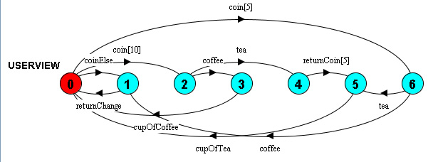
Question: To which states of the informal model correspond the numbered states of the LTSA diagram ?
The following is a model written in the LTSA notation.
CONTROLLER = (coin[5] -> PAIDFIVE | coin[10] -> PAIDTEN | coinElse -> returnChange -> CONTROLLER),
PAIDFIVE = (tea -> MAKETEA | coffee -> returnChange -> CONTROLLER),
PAIDTEN = (tea -> returnCoin[5] -> MAKETEA | coffee -> MAKECOFFEE),
MAKETEA = (cupOfTea -> CONTROLLER),
MAKECOFFEE = (cupOfCoffee -> CONTROLLER).
The following model is more detailed: in addition to the user perspective, the model also identifies two internal components (the CONTROLLER and the HARDWARE that produces the drinks), and the communication between these internal components is described by the interactions {fillWater, waterOK, heatWater, warm, fillCoffee, coffeeOK}. Note: the first three lines of the CONTROLLER definition are the same as above.
CONTROLLER = (coin[5] -> PAIDFIVE | coin[10] -> PAIDTEN | coinElse -> returnChange -> CONTROLLER),
PAIDFIVE = (tea -> MAKETEA | coffee -> returnChange -> CONTROLLER),
PAIDTEN = (tea -> returnCoin[5] -> MAKETEA | coffee -> MAKECOFFEE),
MAKETEA = (fillWater -> waterOK -> heatWater -> warm -> cupOfTea -> CONTROLLER),
MAKECOFFEE = (fillWater -> waterOK -> fillCoffee -> coffeeOK -> heatWater -> warm -> cupOfCoffee -> CONTROLLER).
HARDWARE = (fillWater -> waterOK -> HARDWARE | heatWater -> warm -> HARDWARE | fillCoffee -> PREPARECOFFEE),
PREPARECOFFEE = (coffeeOK -> HARDWARE).
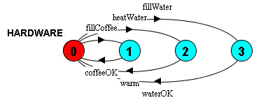
The dynamic behavior of the HARDWARE component is shown by the following LTSA diagram:
How would you model this system using the FSM formalism (with input and output messages) ?
Here is a suggestion. First, we note that the interactions defined in the above model, all have a natural direction of input or output, as follows:
Then we can use a notation similar to LTSA where each transition is characterized by two interactions, one input and one output, separated by "/" (this is an ad hoc notation just invented for these course notes). The dynamic behaviors of the CONTROLLER and the HARDWARE can then be described as follows:
CONTROLLER = (coin[5]/noOutput -> PAIDFIVE | coin[10]/noOutput -> PAIDTEN | coinElse/returnChange -> CONTROLLER),
PAIDFIVE = (tea/fillWater -> TEA1 | coffee -> returnChange -> CONTROLLER),
PAIDTEN = (tea/returnCoin[5] -> noInput/fillWater -> TEA1 | coffee/fillWater -> COFFEE1),
TEA1 = (waterOK/heatWater -> warm/cupOfTea -> CONTROLLER),
COFFEE1 = (waterOK/fillCoffee -> coffeeOK/heatWater -> warm/cupOfCoffee -> CONTROLLER).
HARDWARE = (fillWater/waterOK -> HARDWARE | heatWater/warm -> HARDWARE | fillCoffee/coffeeOK -> HARDWARE).
Mini-exercise: Draw two state diagrams representing the behaviors of the CONTROLLER and HARDWARE FSMs.