University of Ottawa |
SEG-2106 - Lab-1 |
Preliminaries: Please look at these examples:
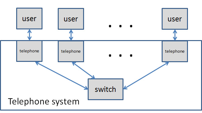
We consider a simple telephone system to be used within a given group of people. We assume that the system consists of a certain number of telephones that are connected to a central switch (either through fixed communication links or through a wireless system). A model of the system structure is given here:
These telephones are used by the people for making calls or receiving calls (according to the standard procedures for establishing telephone connections). We only consider one-to-one telephone conversations, no teleconferencing.
Typically, for establishing a telephone conversation, the user of a telephone picks up the phone, selects the telephone number of the destination party and requests a call to be made. If the telephone at the destination is not busy, the telephone at the destination will ring, while the original user will hear a ring tone in the telephone. If the a user at the destination picks up the phone the two users can talk. The telephone conversation is terminated when one of the telephones is hang up.
Methodology:
Task 1: Please follow this methodology. The textual description (point 1.1 of the Methodology) is given above in the Problem Definition. We consider here the telephone system as a black box, that is, for the points 3 of the Methodology, we consider the interactions between the users and the telephone system.
Note: Point 4 of the methodology will be addressed in Part 2.
Task 2: Here we address Point (4) of the Methodology above. Please define the dynamic behavior of a telephone, as seen by a usert. We only consider the states of a single telephone. It is suggested to describe the dynamic behavior separately for the calling user and for the called user. For this purpose:
Now we consider the internal structure of the telephone system, as shown in the diagram above. It is clear that a telephone not only interacts with a user, but also with the switch. The objective of your work in this Part 3 is to provide a model of the dynamic behavior of a telephone including the interactions with the user (as elaborated above) AND the interactions with the switch component.
Task 3: For this purpose, you should perform the following steps:
The SIP protocol has been defined by the Internet Society (IETF) as a standard protocol for IP-telephony. A SIP-telephone realizes the functions of a SIP user agent. This functionality includes a so-called Client behavior (for initiating a telephone call) and a so-called Server behavior (for receiving a call). A SIP-telephone can directly communicate with another SIP-telephone (if it knows the IP address of the called telephone), but normally the establishment of a telephone call goes through a so-called SIP proxy that plays a role similar to the switch in the telephone system considered above.
The interactions between the SIP-telephones and SIP proxies are classified into SIP Requests (messages sent by a SIP user agent Client and received by a Server) and SIP Responses (messages sent by a SIP user agent Server in response to a SIP Request, and received by a Client).
Task 4: The objective of this Part 4 is to compare your system design (Part 3 above) with SIP. For this purpose, please provide the following:
An overview description of SIP is given in Wikipedia. A more detailed description was given by the main authors of the SIP protocol in the journal article "Internet Telephony: architecture and protocols – an IETF perspective". I think, for the purpose of this Lab work, it is sufficient to read this extract from the article of the Wikipedia. Here is a summary explanation of the diagram that is shown at the end: This diagram shows the establishment of a connection between the telephone (user agent) "sip:user1@here.com" and the telephone of the destination. "sip:user1@here.com" first sends an Invite message to "SIP Stateful Proxy 1" who does not know how to find the destination and therefore tries to find this information by forwarding the Invite message to the "SIP Redirect Server" who sends back the "Moved temporarily" response message including the efffective address of the destination user, which is "sip:user2@there.com". Then the "SIP Stateful Proxy 1" sends an Invite message with the effective destination address through two other proxies until the destination is reached. The telephone user agent of the destination returns the "200 OK" response which finally reaches the calling user agent. The latter then sends an ACK Request to confirm that the OK response was received. Thereafter the connection is established and the voice traffic goes directly between "sip:user1@here.com" and "sip:user2@there.com".
It is to be noted that the specification of the SIP protocol does not talk about the interactions with the user. It only talks about the interactions of a SIP-telephone with another SIP-telephone or with a SIP proxy. (Note: Because the user interactions are not defined, it is sometimes not clear what the meaning of the defined telephone-to-telephone interactions are.)
Your lab report shoukl report on your results for the four tasks above.
The (preliminary) marking scheme is as follows:
Please consult with the TA during the Lab session. The role of the TA is to help you to do the work suggested within this Lab.