Transition: From the current state to another state, the next state (or destination state)
UML parlance: An event triggers a state transition. An action may be associated with a transition or with a state (do-action).
UML State vs Activity diagram: Example (from SEG-2106 course notes)
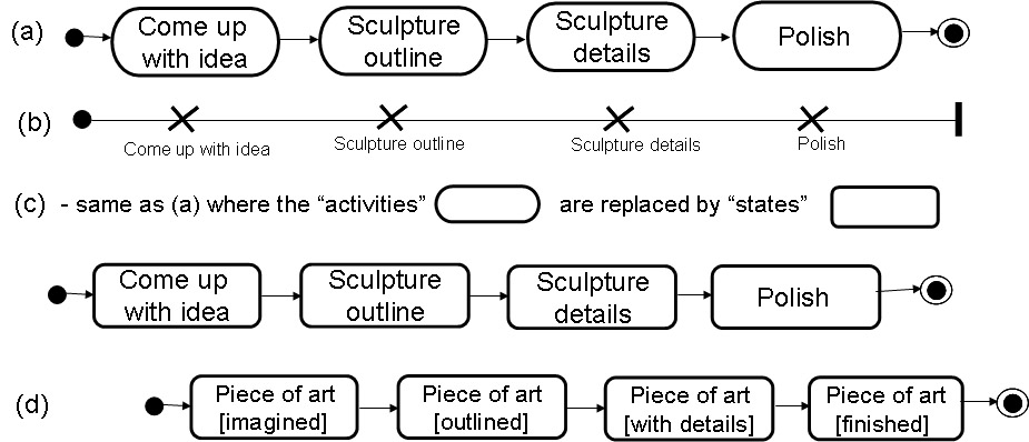
As an example, we consider the process by which an artist creates a wood sculpture (I remember, I did this when I was young): (1) the artist comes up with an idea of a sculpture, (2) s/he takes a piece of wood and prepares an outline of the sculpture, (3) the sculpture is refined in detail, and finally, (4) the sculpture is polished (and can be admired). Here are several representations of this process: (a) a UML Activity diagram, (b) a Use Case Map (UCM), (c) a UML State diagram representing the states of the artist working on the project, and (d) a UML State diagram representing the states of the sculpture. Note that diagrams (a), (b) and (c) have exactly the same meaning, while diagram (d) shows the process from another perspective, namely from the point of view of the object that is manipulated. In diagrams (a) through (c), the transitions between the activities/states are short, while some longer time periods are spent during the activities shown in the diagram (or the actions implied by the name of the states - in diagram (c)). In the perspective of the manipulated object (diagram (d)), the transitions take some longer time, while the states represent milestones - identifyable states of the object during the creating process. I would say that the diagrams (a) through (c) are action-oriented models, while diagram (d) is state-oriented. If we compare diagrams (c) and (d), we see that actions become states and states become actions. It is important to note that these two approaches can be used for describing the same reality. Which of these two approaches is better depends on the purpose of modeling.
In other words:
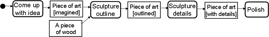
The same reality can also be represented by the UML Activity diagram below including object (data) flow. This diagram includes both views, the action-oriented and the state-oriented one. Here the data objects (represented by the rectangulars) represent the sculpture in its different states. Note: Here the transitions are associated with data objects that are produced by one action and consumed by the next action - they are actually inputs and outputs for these actions, namely the activities in the diagram.
Formal state-transition modeling:
Labelled transition system (LTS): Has a finite number of states; transitions are labelled by actions names. Example: Door that locks
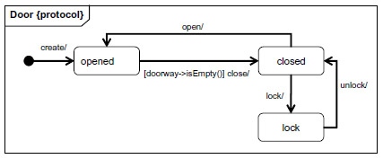
Rendezvous communication: Different LTS communicate by doing respective transitions with the same label simultaneously (only if both LTS are in a state where a transition with that label is possible).
Sometimes one distinguishes input (?) and output (!) labels - an output transition, say !out1, of one component is performed simultaneously with corresponding input transitions ?out1 of one or several other components - in this case, the LTS is sometimes called Input-Output Automaton (IOA). - Semantics of input-output: A component may take the initiative for performing an output transitions, but not for an input transition; the latter has to wait until it can make a rendezvous with a corresponding output transition of another system component. Example: The user of the door and the door do the above transitions in rendezvous - at the same time - and the user cannot perform the lock transition when the door is in the opened state. In this case the user actions may be considered output and the labels of the door as inputs.
Communication by interactions - Different kinds of interactions:
Interleaving semantics vs concurrency:
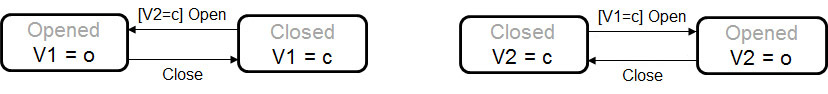
Communication by variables - Finite State Machine (FSM) of type Moore: Has input and output - output can be modelled by variables. Value of output depends on state; the value of input may determine which transition will be executed - transitions may have input conditions. Example of Door that locks - modelled as two state machines that communicate by two input-output variables V1 and V2:
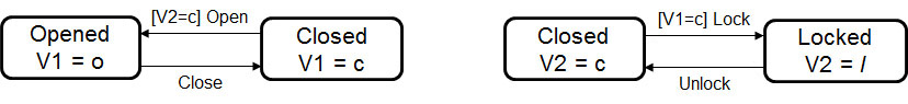
Another example that has the same behavior pattern - only the (informal) meaning of actions associated with the transitions of the second FSM are different: This example represents two doors that cannot be opened simultaneously. Note: The names of the states has no formal meaning (therefore only shown in grey) - but it may be helpful for human understanding.
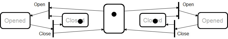
Petri nets: Generalization of LTS - transition may require tokens from more than one state - and may produce tokens for more than one destination state. In some sense, each token represents a point of execution, but their number is not fixed.
Finite State Machine (FSM) - Mealy type: Like Moor machines, except that inputs and outputs are messages (also called events, signals). Usually, one considers that the messages will be in transit (modelled as a message queue) before they are consumed as input by the destination FSM. Such a system is usually called Communicating FSMs. If there is no queuing of message, but messages are received as soon as they are produced, then this is equivalent to the IOA modeling paradigm.
Created: September 9, 2015