Here we consider that a system consists of several components and each component is described as a transition system. The question that arises is how can the behavior of the composed system be characterized. This can be answered by reachability analysis, finding out what global system states can be reached by the system from its initial state.
Before we can perform reachability analysis, we have to determine how we can model the system as a whole. The idea is to model it again as a transition system. The transitions of the global system correspond to the transitions of the components, and the state space of the global system is determined by the state spaces of the components. Let us suppose that the global system consists out of n components Ci (i = 1, ..., n) and that the state spaces of these components are Si (i = 1, ..., n). The LTS components communicate by rendezvous - there are no messages in transit between the components. Therefore the state space of the global system S is given by the Cartesian product of the component state spaces, that is, S = S1 x S2 x ... x Sn. This means, that a particular state of the global system has the form <s1, s2, ..., sn> where si is a state in Si (for i = 1, ..., n).. Note: If in a given system state, the global system also contains some messages in transit, then the state of the message transmission medium (in terms of what messages are in transit to which destination) must also be taken into account. This complication is discussed in a later chapter.
For simplifying the exposition, we assume in the following that the global system consists of two components C1 and C2.
Before we can perform a reachability analysis, we have to determine for each transition of C1 what are the transitions of C2 with which it is to be executed in rendezvous. There are different ways for specifying which pair of transitions must be performed in rendezvous. A simple approach is to list these pairs explicitely << see for instance in the work by André Arnold; for instance his book Finite Transition Systems: Semantics of Communicating Systems >>, while the others can be executed by each component separately. Another approach requires matching identically named transitions. This was adopted in languages such as CSP, CCS and LOTOS. In the following, we will assume that transitions of different components that have the same name must be executed in rendezvous.
To simplify the following formalism, we introduce the concept of the alphabet of a state transition model. This is the set of all transition names of the model. For LTS, the name of the transition is the label of the transition. We write s1 -- a --> s1' for a transition where s1 and s1' are states and a is a transition name in the alphabet.
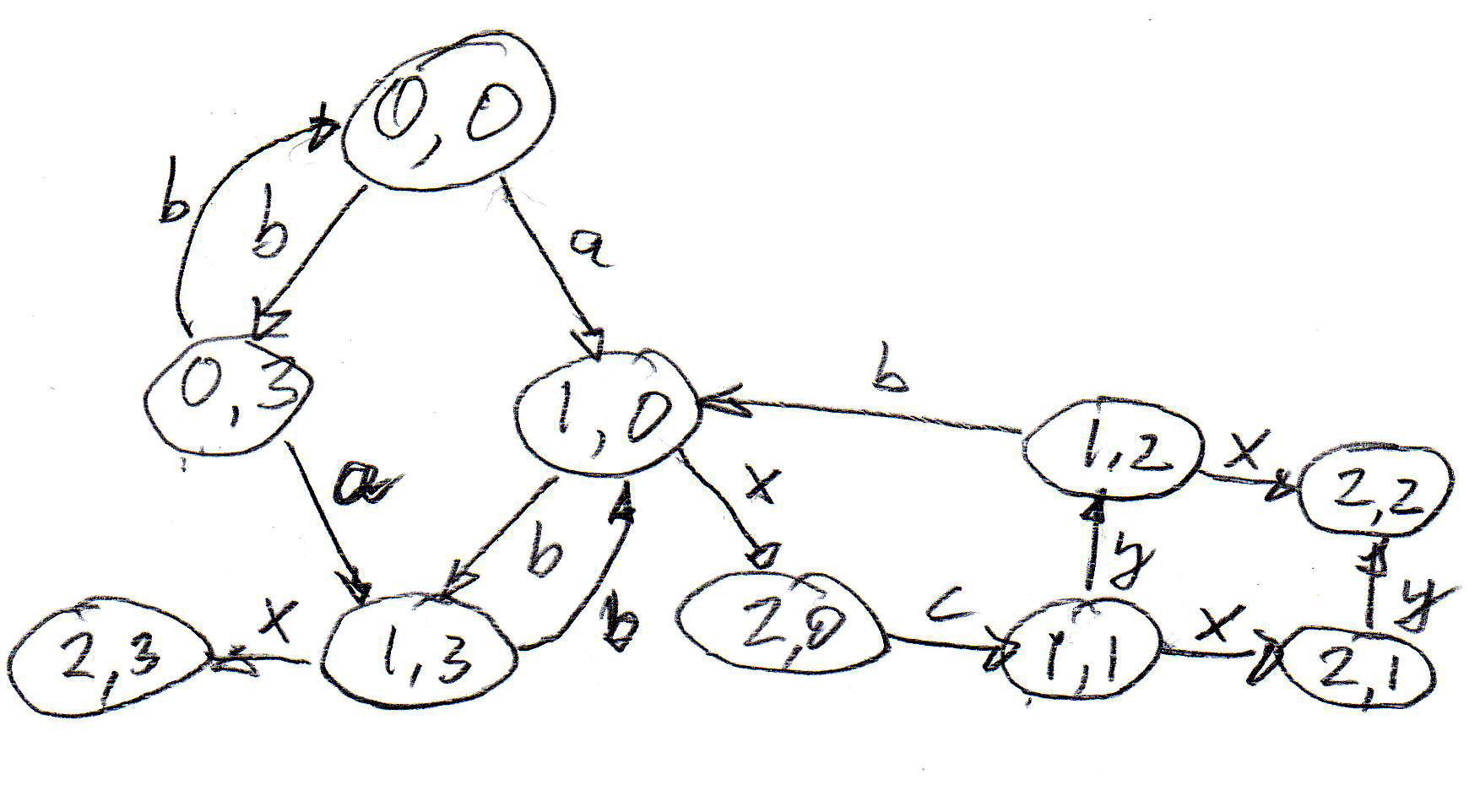
The composition of two LTS models, C1 and C2, with alphabet A1 and A2, respectively, can be modeled by an LTS that represents the behavior of these two LTS and their interactions, in the following called C. The model of C is the following LTS:
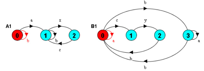
Example: Alphabet of A1: a, b, c and x - alphabet of B1: a, b, c and y - rendezvous for a, b, c - x and y are executed separately. The behavior of the composition has two deadlocks.
As this example shows, reachability analysis of a composed system is useful for pin-pointing design flaws that are not evident from the separate inspection of the component behaviors. Unfortunately, the number of reachable states of the composed behavior is often very large.
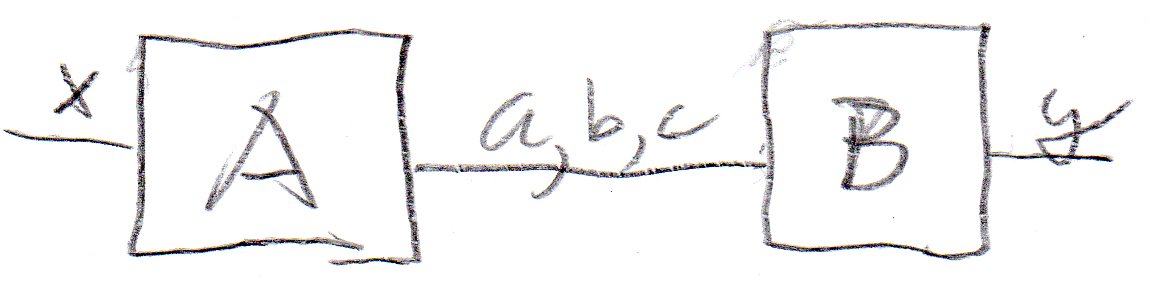
Before going into the details of the dynamic behavior of a composed system, it is usually suggested to first consider the static structure of the system, identifying the components in the system and the interfaces through which they communicate, including the list of interactions that may occur on each of these interfaces (and the direction in case of input-output interactions). A UML Component diagram can be used for this purpose. In this course notes, we use a simplified notation, as shown below for the architecture of the example above. This architecture diagram shows clearly that the two components communicate using the interactions a, b and c, and that the interactions x and y are performed with the environment of the system.
Created: September 2, 2014