Given: September 16 - Due: September 23 (please bring your solution on paper to the class). Hand drawings are OK if they are clearly presented.
Let us assume that loan requests submitted by clients are processed by the bank as follows: A client who wants to obtain a load must first fill in a load request form. The form will be checked by a loan clerc for completeness. If it is not complete, the missing information will be obtained (possibly through a telephone conversation). When the form is complete, it will be passed to the loan manager who decides whether the loan can be granted or not. In same cases, the manager requires some additional information, in which case the client has to fill in an additional form. This form will again be checked for completeness by the clerc and passed on to the manager if it is complete. If the load is accepted, the client will be informed and the bank provides the money and looks after the reimbursment over time. If the loan is not accepted, the client will be informed and the load request will be stored in a database.
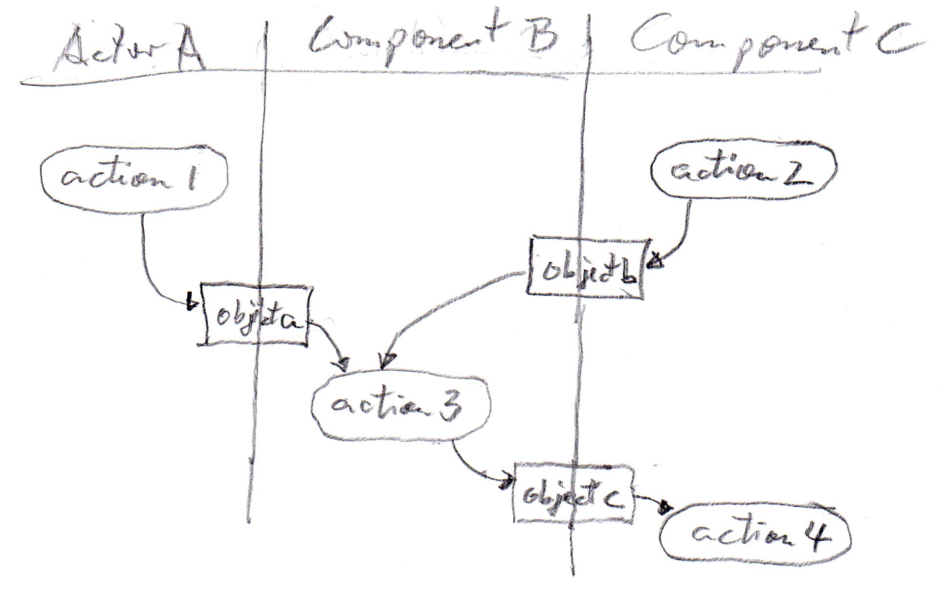
Write down a UML Activity diagram with several swimlanes, one swimlane for each actor (or component) involved in this workflow. The diagram should not only show the control flow of this application, but also the objects that flow between the different activities.
If you think that the description given above is not precise, please make your own assumptions and write down what kind of additional assumptions you have made.
Here is an example of an extract of an activity diagram with smimlanes and object flow:
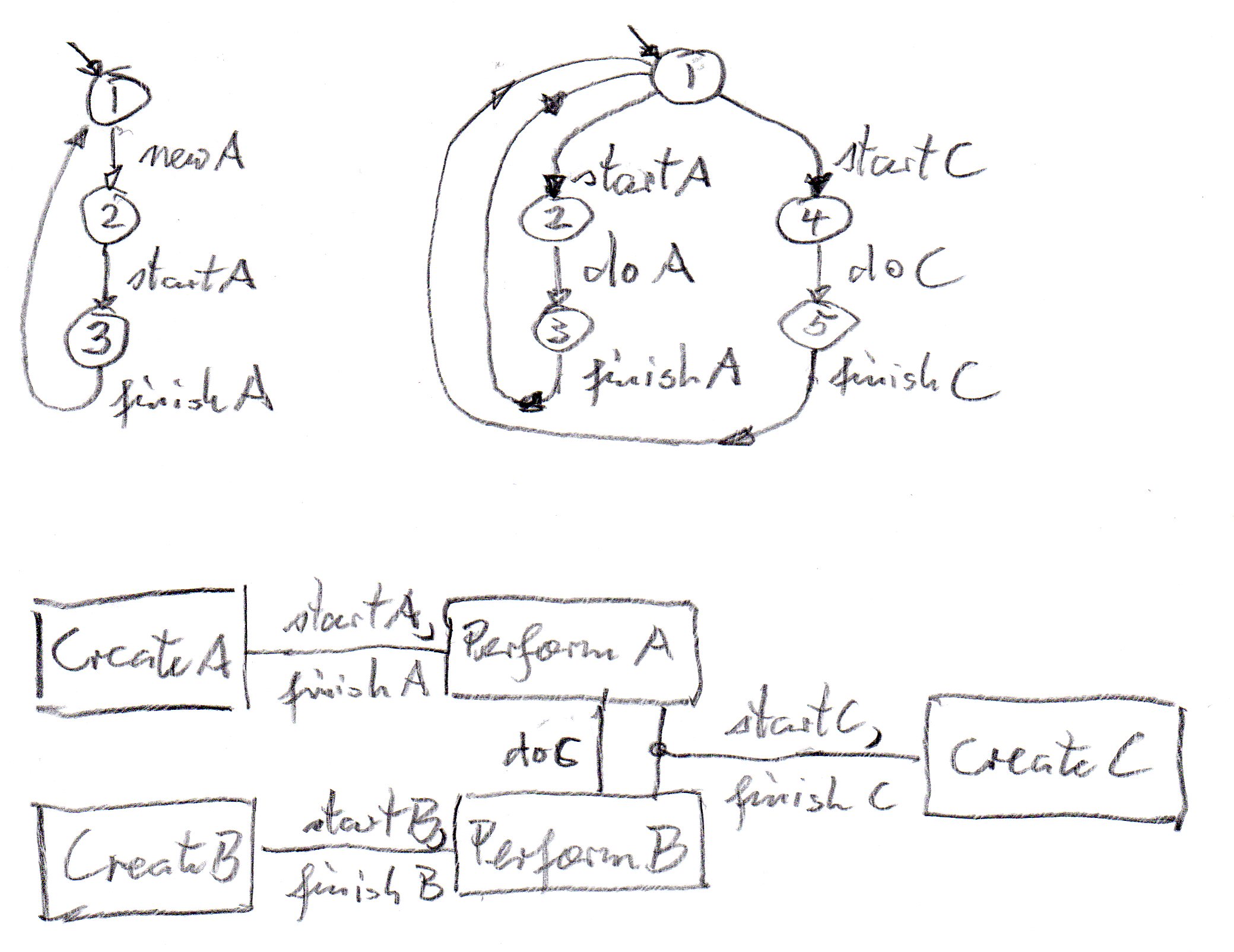
We consider a system which processes three types of jobs: A, B and C. The system consists of 5 components, three job creation components, one for each type of job, and two processing components, one for jobs A and C, and one for jobs B and C. The jobs of type C are "big" jobs and require both processing components at the same time.
Below (on the left) you find an LTS describing the order of interactions of the job creation component for jobs of type A, called CreateA. The behavior of the job creation components for the other types of jobs are similar. The behavior starts with the interaction newA, followed by startA, followed by finishA and then this behavior repeats.
You also find the behavior of the processing component for jobs A and C, called PerformA (on the right side). It has a choice in the initial state, starting its behavior either with a startA interaction or a startC interaction. Afterwards, it executes a doA (or doC) interaction and then a finishA (or finishC) interaction. The behavior of the PerformB component is similar (it performs B types of jobs, instead of A).
The last diagram (further below) shows the overall architecture of the system. You may consider this a UML Class diagram where the lines between classes represent relationships, and these relationships are annotated with the interactions that are jointly executed by the class instances that are connected by these lines. Please note that startC and finishC are three-way interactions executed jointly by CreateC, PerformA and PerformB, and the interactions newA and doA (similar for newB, doB and newC) are local (internal) interactions of one component (which can be executed whenever the component is in a state where a transition labelled with this interaction is enabled). The interaction doC is a rendezvous between PerformA and PerformB.