Magnetic
Field in an Inductor
If the wire in a coil carries
a current I and the turns are closely spaced,
the coil can produce a relatively uniform
magnetic field within its interior region,
and its magnetic field pattern resembles
that of a permanent magnet.
If the coil length l is
much larger than its radius a, then the
induced magnetic flux density B will be
defined as
Where N
= nl is the total number of
turns over the length l.
Current Flow in
an Inductor
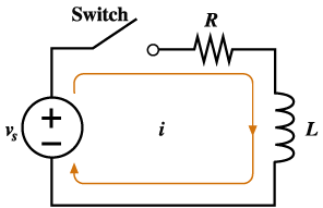
Consider the RL circuit shown in
Figure 13.2.
-
At the time the switch is closed, the
magnetic energy is zero.
-
This means the current in the inductor
is zero.
-
Since there is no current flow, there
is no voltage drop across the resistor.
-
This means initially that the source
voltage appears directly across the
inductor
-
As the current increases, the voltage
drop across the resistor increases.
-
The sum of the voltages across the
inductor and resistor is equal to the
source voltage.
-
As time increases, the voltage across
the resistor increases and the voltage
across the inductor decreases.
-
After a long time, the entire voltage
appears across the resistor and there
will be no voltage across the inductor.

Figure 13.2 Current
in an RL circuit
|