Exercise
What is the current, voltage,
and power for each element of the
circuit shown in Figure 11.2?
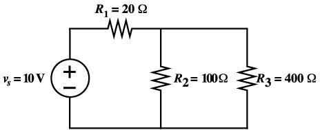
Figure 11.2 Circuit diagram
of series-parallel resistors.
Type your solution in the box below:
Solution:
First combine the two resistances (R2
and R3) in parallel to obtain
the following circuit.
Replacing R2 and R3 by their parallel
equivalent, we obtain the circuit
shown in Figure 11.3
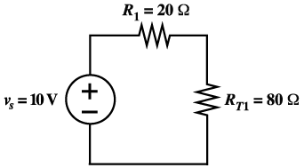
Figure 11.3 Circuit after replacing
R2 and R3 with
RT1.
Notice that R1 and RT1
are in series. Let’s replace these
resistances by their equivalent (sum)
RT as shown in the circuit
in Figure 11.4.
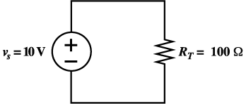
Figure 11.4 Circuit after replacing
R1 and RT1by their
equivalent RT
After reducing the circuit to an equivalent
resistance and a source, we may apply
Ohm’s law to find the current
through the equivalent resistance.
We know that this current flows downward
(from plus to minus) through RT.
This means that the current 0.1 A flows
clockwise around the circuit.
Because RT is the equivalent resistance
seen by the source in all three parts
of Figure 11.5, the current through
V must be i1= 0.1 A flowing
upward in all three equivalent circuits.
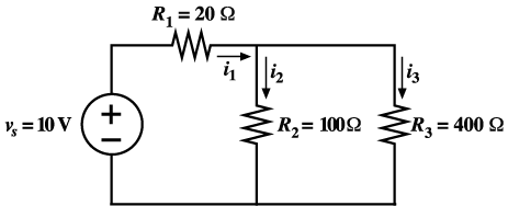
Figure 11.5 Circuit
Look at the circuit shown in Figure
11.6 to realize that the current i1
flows through the source vs and the
equivalent resistance RT1.
The voltage across RT1 can
be found by applying Ohm’s law
again
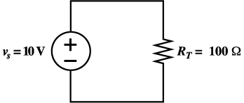
Figure 11.6 Circuit
Since RT1 is the equivalent
resistance for the parallel combination
of R2 and R3,
the voltage v2 appears across
both R2 and R3in
Figure 11.6.
As a check, apply KCL to verify that
i 1 = i2 + i3.
Also we can apply Ohm’s law to
calculate v1
As a check, apply KVL to verify that
v s = v1 + v2.
Now, we compute the power for each element.
For the voltage source vs,
we have
We have included the minus sign because
the references for vsand
i1 are opposite to the passive
configuration. Since the power for the
source is negative, this means that
the source is supplying energy to the
other elements in the circuit.
The powers for the resistors are
As a check, we verify that ps
+ p1 + p2 + p3
= 0, showing that power is conserved.

|