Kirchhoff’s Voltage Law (KVL)
The algebraic sum of the
voltage drops in any closed path in a circuit
and the electromotive forces in that path
are equal to zero. In traveling around a
closed path, we encounter various voltages,
some of which carry a positive sign while
others carry a negative sign in the algebraic
sum.
- A convenient convention is to use the
first polarity mark encountered for each
voltage to decide if it should be added
or subtracted in the algebraic sum.
- If we go through the voltage from the
negative polarity reference to the positive
reference, it carries a minus sign.
- If the polarity marks are encountered
in the opposite direction (plus to minus),
the voltage carries a negative sign.
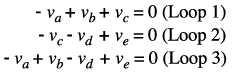
For the circuit of Figure 8.2, we obtain
the following equations:
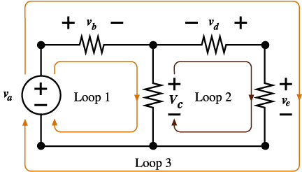
Figure
8.2 Circuit showing three closed paths to
illustrate Kirchhoff’s
Voltage
Law (KVL).
KVL may be applied
to a simple closed-loop circuit taking into
account the following guidelines:
-
For a voltage source, the assumed
loop current flow from – to
+ is considered positive and is given
the + sign.
-
For a voltage source, the assumed
loop current flow from + to - is considered
negative and is given the - sign.
-
The direction of the assumed loop
current is always positive. Therefore,
the current enters the resistance
from the positive side and leaves
from the negative side.
-
The polarity of a voltage source
is not changed by the direction of
the assumed loop current.
|